Toyota Camry (XV70): Installation
INSTALLATION
CAUTION / NOTICE / HINT
HINT:
- Use the same procedure for the RH side and LH side.
- The following procedure is for the LH side.
PROCEDURE
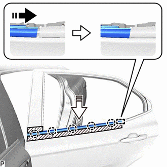
1. INSTALL REAR DOOR BELT MOULDING ASSEMBLY
(a) Engage the guide and 5 claws to install a new rear door belt moulding assembly as shown in the illustration.
.png) |
Install in this Direction (1) |
.png) |
Install in this Direction (2) |
2. INSTALL REAR DOOR GLASS SUB-ASSEMBLY
Click here
.gif)
3. INSTALL REAR DOOR QUARTER WINDOW GLASS
Click here
4. INSTALL REAR DOOR REAR LOWER WINDOW FRAME SUB-ASSEMBLY
Click here
5. CONNECT REAR DOOR WEATHERSTRIP
Click here
6. INSTALL REAR DOOR GLASS RUN
Click here
7. INSTALL REAR DOOR PANEL PROTECTOR
Click here
8. INSTALL REAR DOOR NO. 1 VENT SEAL
Click here
9. INSTALL REAR DOOR SERVICE HOLE COVER
Click here
10. INSTALL REAR DOOR NO. 2 SERVICE HOLE COVER
Click here
11. INSTALL REAR DOOR INNER GLASS WEATHERSTRIP
Click here
12. INSTALL REAR DOOR TRIM BOARD SUB-ASSEMBLY
Click here
13. INSTALL REAR ARMREST ASSEMBLY
Click here
14. INSTALL REAR POWER WINDOW REGULATOR SWITCH ASSEMBLY WITH REAR DOOR UPPER ARMREST BASE PANEL
Click here
15. INSTALL REAR DOOR ARMREST COVER SUB-ASSEMBLY
Click here
16. CONNECT CABLE TO NEGATIVE BATTERY TERMINAL
for A25A-FKS:
Click here
for 2GR-FKS:
Click here
17. INITIALIZE POWER WINDOW CONTROL SYSTEM
Click here
18. INSPECT POWER WINDOW OPERATION
Click here
READ NEXT:
 Components
COMPONENTS ILLUSTRATION
*1 REAR DOOR FRONT WINDOW FRAME MOULDING
*2 REAR DOOR WEATHERSTRIP
*3 REAR DOOR WINDOW FRAME MOULDING SUB-ASSEMBLY
*4 RIVET
Removal
REMOVAL CAUTION / NOTICE / HINT
The necessary procedures (adjustment, calibration, initialization or registration) that must be performed after parts are removed and installed, or replaced during r
SEE MORE:
Components
COMPONENTS ILLUSTRATION
*1 REAR ENGINE UNDER COVER LH
*2 FRONT FENDER APRON SEAL LH
*3 NO. 1 ENGINE UNDER COVER
*4 FRONT WHEEL OPENING EXTENSION PAD LH
*5 FRONT WHEEL OPENING EXTENSION PAD RH
- -
N*m (kgf*cm, ft.*lbf): Specified
Removal
REMOVAL CAUTION / NOTICE / HINT
The necessary procedures (adjustment, calibration, initialization or registration) that must be performed after parts are removed and installed, or replaced during knock control sensor removal/installation are shown below. Necessary Procedures After Parts Removed/In
