Toyota Camry (XV70): Removal
REMOVAL
CAUTION / NOTICE / HINT
The necessary procedures (adjustment, calibration, initialization or registration) that must be performed after parts are removed and installed, or replaced during rear door window frame moulding removal/installation are shown below.
Necessary Procedure After Parts Removed/Installed/Replaced|
Replaced Part or Performed Procedure |
Necessary Procedure | Effect/Inoperative Function when Necessary Procedure not Performed |
Link |
|---|---|---|---|
|
Disconnect cable from negative battery terminal |
Perform steering sensor zero point calibration |
Lane Tracing Assist System |
|
|
Pre-collision System | |||
|
Memorize steering angle neutral point |
Parking Assist Monitor System |
| |
|
Panoramic View Monitor System |
| ||
| Initialize power window control system |
|
|
HINT:
- Use the same procedure for the RH side and LH side.
- The following procedure is for the LH side.
PROCEDURE
1. REMOVE REAR DOOR BELT MOULDING ASSEMBLY
Click here .gif)
2. DISCONNECT REAR DOOR WEATHERSTRIP
| (a) Disengage the 2 clips and disconnect the rear door weatherstrip. |
|
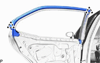
3. REMOVE REAR DOOR FRONT WINDOW FRAME MOULDING
HINT:
When removing the rear door front window frame moulding, heat the vehicle body and rear door front window frame moulding using a heat light.
Heating Temperature|
Item | Temperature |
|---|---|
|
Vehicle Body | 40 to 60 |
READ NEXT:
 Installation
INSTALLATION CAUTION / NOTICE / HINT
HINT:
Use the same procedure for the RH side and LH side.
The following procedure is for the LH side.
PROCEDURE 1. INSTALL REAR DOOR WINDOW FRAM
Components
COMPONENTS ILLUSTRATION
*A except TRD
*B for TRD
*1 LUGGAGE COMPARTMENT DOOR COVER
*2 REAR SPOILER
*3 REAR SPOILER RETAINER
- -
SEE MORE:
Disassembly
DISASSEMBLY CAUTION / NOTICE / HINT
NOTICE: Before installation of each part, thoroughly clean and dry it. Then apply gear oil to it. Do not use alkaline chemicals to clean aluminum parts, rubber parts or ring gear set bolts. Also, do not use non-residue solvent or other cleaning oils to clean O-r
ABS Warning Light does not Come ON
DESCRIPTION The skid control ECU (brake actuator assembly) controls the ABS warning light in the combination meter assembly via CAN communication. CAUTION / NOTICE / HINT
NOTICE: After replacing the skid control ECU (brake actuator assembly), perform acceleration sensor zero point calibration and
