
Toyota Camry (XV70): Installation
INSTALLATION
PROCEDURE
1. ADJUST COMPRESSOR OIL
(a) When replacing the compressor assembly with pulley with a new one, gradually discharge the inert gas (helium) from the service valve, and drain the following amount of oil before installation.
NOTICE:
- If a new compressor assembly with pulley is installed without removing the same amount of compressor oil as is remaining in the pipes, the amount of compressor oil will be excessive. This prevents heat exchange in the refrigerant cycle and will cause the air conditioning system to malfunction.
- A certain amount of compressor oil remains in the compressor assembly with pulley during circulation and the compressor may be damaged if the amount of compressor oil is more/less than this amount. Therefore, make sure to adjust the amount of compressor oil correctly.
- If the amount of compressor oil remaining in the removed compressor assembly with pulley is excessively low, check for compressor oil leaks.
- Do not race the engine before replacing the compressor assembly with pulley.
- Make sure to use ND-OIL 12 or equivalent compressor oil.
| (b) Remove the drain bolt (seal washer) from the removed compressor assembly with pulley. |
|
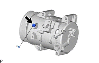
(c) Drain the compressor oil from the oil port of the removed compressor assembly with pulley as shown in the illustration.
NOTICE:
Make sure to drain the compressor oil from the oil port.
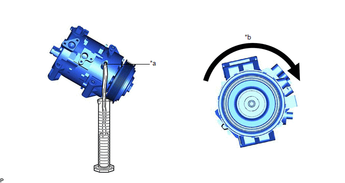
|
*a | Oil Port |
*b | Turn Clockwise |
| (d) Remove the drain bolt (seal washer) from a new compressor assembly with pulley. HINT: The drain bolt (seal washer) can be reused. |
|
(e) Drain the following amount of compressor oil from the oil port of the new compressor assembly with pulley as shown in the illustration.
Standard:
(The amount of oil in a new compressor assembly with pulley: 70 (+15) cc (2.37 (+0.51) fl.oz)) - (The amount of oil in the removed compressor assembly with pulley) = The amount of oil to be removed from the new compressor assembly with pulley.
NOTICE:
- Make sure to drain the compressor oil from the oil port.
- Make sure to add the compressor oil from the oil port, not from the discharge or intake port.
- If a tool is used to add compressor oil to the new compressor assembly with pulley, make sure that it is free of foreign matter.
- If the amount of compressor oil remaining in the removed compressor assembly with pulley cannot be estimated because the compressor was damaged and oil was discharged due to a frontal collision, etc., install a new compressor assembly with pulley without removing any oil. If the cooler condenser assembly is also replaced, do not add the specified amount of compressor oil for cooler condenser assembly replacement (40 cc (1.35 fl.oz)).
|
*a | Oil Port |
*b | Turn Clockwise |
(f) Install the drain bolt (seal washer) to the new compressor assembly with pulley.
Torque:
30 N·m {306 kgf·cm, 22 ft·lbf}
NOTICE:
Make sure that there is no damage or foreign matter on the seal washer edge.
2. INSTALL COMPRESSOR ASSEMBLY WITH PULLEY
(a) for Type A:
(1) Using an E8 "TORX" socket wrench, temporarily install the compressor assembly with pulley with the 2 stud bolts.
Torque:
5.0 N·m {51 kgf·cm, 44 in·lbf}
(2) Install the compressor assembly with pulley with the 2 bolts and 2 nuts.
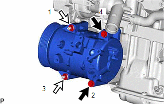
.png) |
Bolt |
.png) |
Nut |
Torque:
24.5 N·m {250 kgf·cm, 18 ft·lbf}
HINT:
Tighten the bolts and nuts in the order shown in the illustration.
(b) for Type B:
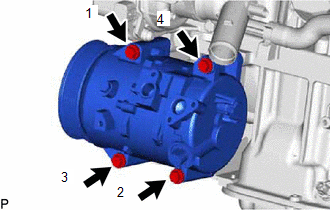
| (1) Install the compressor assembly with pulley with the 4 bolts. Torque: 24.5 N·m {250 kgf·cm, 18 ft·lbf} HINT: Tighten the bolts in the order shown in the illustration. |
|
(c) Connect the 2 connectors.
3. CONNECT SUCTION HOSE SUB-ASSEMBLY
(a) Remove the vinyl tape from the suction hose sub-assembly.
(b) Sufficiently apply compressor oil to a new O-ring and the fitting surface of the compressor assembly with pulley.
Compressor Oil:
ND-OIL 12 or equivalent
(c) Install the O-ring to the suction hose sub-assembly.
NOTICE:
Keep the O-ring and O-ring fitting surface free of foreign matter.
(d) Connect the suction hose sub-assembly to the compressor assembly with pulley with the bolt.
Torque:
9.8 N·m {100 kgf·cm, 87 in·lbf}
4. CONNECT NO. 1 COOLER REFRIGERANT DISCHARGE HOSE SUB-ASSEMBLY
(a) Remove the vinyl tape from the No. 1 cooler refrigerant discharge hose sub-assembly.
(b) Sufficiently apply compressor oil to a new O-ring and the fitting surface of the compressor assembly with pulley.
Compressor Oil:
ND-OIL 12 or equivalent
(c) Install the O-ring to the No. 1 cooler refrigerant discharge hose sub-assembly.
NOTICE:
Keep the O-ring and O-ring fitting surface free of foreign matter.
(d) Connect the No. 1 cooler refrigerant discharge hose sub-assembly to the compressor assembly with pulley with the bolt.
Torque:
9.8 N·m {100 kgf·cm, 87 in·lbf}
5. CONNECT NO. 5 WATER BY-PASS HOSE
Click here .gif)
6. INSTALL INLET AIR CLEANER ASSEMBLY
Click here
7. INSTALL COOL AIR INTAKE DUCT SEAL
Click here
8. INSTALL V-RIBBED BELT
Click here
9. ADD ENGINE COOLANT
Click here
10. INSPECT FOR COOLANT LEAK
Click here
11. CHARGE AIR CONDITIONING SYSTEM WITH REFRIGERANT
Click here
12. WARM UP ENGINE
Click here
13. INSPECT FOR REFRIGERANT LEAK
Click here
READ NEXT:
SEE MORE:
 2gr-fks Drive Belt
ComponentsCOMPONENTS ILLUSTRATION
*1 FRONT FENDER APRON SEAL RH
*2 V-RIBBED BELT RemovalREMOVAL PROCEDURE
1. REMOVE FRONT WHEEL RH Click here
2. REMOVE FRONT FENDER APRON SEAL RH
Click here
3. REMOVE V-RIBBED BELT
(a) Release the V-ribbed belt tension
How To Proceed With Troubleshooting
CAUTION / NOTICE / HINT
HINT:
Use the following procedure to troubleshoot the audio and visual system.
*: Use the Techstream.
PROCEDURE
1. VEHICLE BROUGHT TO WORKSHOP
NEXT
2.
CUSTOMER PROBLEM ANALYSIS
When troubleshooting, c
