
Toyota Camry (XV70): Blower Motor Circuit
DESCRIPTION
The blower motor with fan sub-assembly is operated by signals from the air conditioning amplifier assembly. Blower motor speed signals are transmitted in accordance with changes in the duty ratio.
If the airflow volume is low or the blower speed cannot be changed, the following suspected areas may be the cause.
|
Symptom | Factor |
|---|---|
|
|
WIRING DIAGRAM
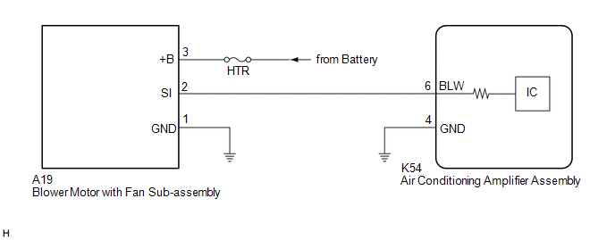
CAUTION / NOTICE / HINT
NOTICE:
Inspect the fuses for circuits related to this system before performing the following procedure.
PROCEDURE
| 1. |
PERFORM ACTIVE TEST USING TECHSTREAM |
(a) Connect the Techstream to the DLC3.
(b) Turn the ignition switch to ON.
(c) Turn the Techstream on.
(d) Enter the following menus: Body Electrical / Air Conditioner / Active Test.
(e) Perform the Active Test according to the display on the Techstream.
Body Electrical > Air Conditioner > Active Test|
Tester Display | Measurement Item |
Control Range | Diagnostic Note |
|---|---|---|---|
|
Blower Motor | Blower motor with fan sub-assembly |
Min.: 0 Max.: 31 |
- |
|
Tester Display |
|---|
| Blower Motor |
| Result |
Proceed to |
|---|---|
| Blower motor with fan sub-assembly does not operate |
A |
| Blower motor with fan sub-assembly operates but does not change speed |
B |
| B |
.gif) | GO TO STEP 6 |
|
.gif)
| 2. |
CHECK HARNESS AND CONNECTOR (BLOWER MOTOR WITH FAN SUB-ASSEMBLY - BODY GROUND) |
(a) Disconnect the A19 blower motor with fan sub-assembly connector.
(b) Measure the resistance according to the value(s) in the table below.
Standard Resistance:
|
Tester Connection | Condition |
Specified Condition |
|---|---|---|
|
A19-1 (GND) - Body ground |
Always | Below 1 ? |
| NG | | REPAIR OR REPLACE HARNESS OR CONNECTOR |
|
| 3. |
CHECK HARNESS AND CONNECTOR (BLOWER MOTOR WITH FAN SUB-ASSEMBLY - BATTERY) |
(a) Measure the voltage according to the value(s) in the table below.
Standard Voltage:
|
Tester Connection | Condition |
Specified Condition |
|---|---|---|
|
A19-3 (+B) - Body ground |
Always | 11 to 14 V |
| NG | | REPAIR OR REPLACE HARNESS OR CONNECTOR |
|
| 4. |
CHECK HARNESS AND CONNECTOR (BLOWER MOTOR WITH FAN SUB-ASSEMBLY - AIR CONDITIONING AMPLIFIER ASSEMBLY) |
(a) Disconnect the K54 air conditioning amplifier assembly connector.
(b) Measure the resistance according to the value(s) in the table below.
Standard Resistance:
|
Tester Connection | Condition |
Specified Condition |
|---|---|---|
|
A19-2 (SI) - K54-6 (BLW) |
Always | Below 1 ? |
|
A19-2 (SI) or K54-6 (BLW) - Other terminals and body ground |
Always | 10 k? or higher |
| NG | | REPAIR OR REPLACE HARNESS OR CONNECTOR |
|
| 5. |
INSPECT BLOWER MOTOR WITH FAN SUB-ASSEMBLY |
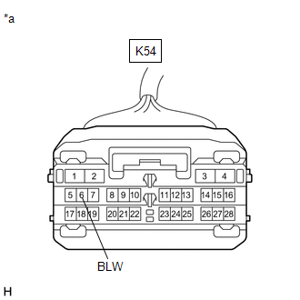
|
*a | Front view of wire harness connector (to Air Conditioning Amplifier Assembly) |
(a) Connect the A19 blower motor with fan sub-assembly connector.
(b) Measure the voltage according to the value(s) in the table below.
Standard Voltage:
|
Tester Connection | Condition |
Specified Condition |
|---|---|---|
|
K54-6 (BLW) - Body ground |
Always | 4.75 to 5.25 V |
| NG | | REPLACE BLOWER MOTOR WITH FAN SUB-ASSEMBLY |
|
| 6. |
INSPECT AIR CONDITIONING AMPLIFIER ASSEMBLY |
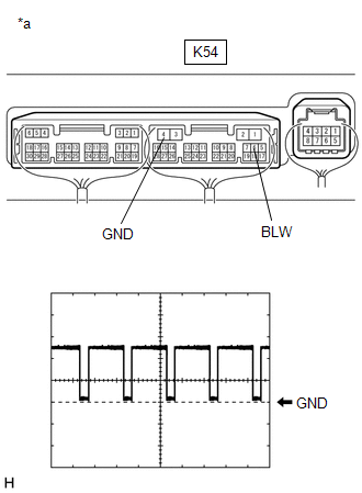
|
*a | Component with harness connected (Air Conditioning Amplifier Assembly) |
(a) Connect the K54 air conditioning amplifier assembly connector.
(b) Turn the ignition switch to ON.
(c) Set the blower speed to LO.
(d) Using a Techstream, check the waveform.
|
Item | Content |
|---|---|
|
Terminal No. | K54-6 (BLW) - K54-4 (GND) |
|
Tool Setting | 2 V/DIV., 1 ms./DIV. |
|
Condition |
|
OK:
Waveform is similar to that shown in the illustration.
HINT:
The waveform varies with the blower speed.
| OK | | REPLACE BLOWER MOTOR WITH FAN SUB-ASSEMBLY |
| NG | | REPLACE AIR CONDITIONING AMPLIFIER ASSEMBLY |
READ NEXT:
 Air Conditioning Compressor Magnetic Clutch Circuit
DESCRIPTION When the engine is running, If refrigerant pressure does not decrease when the A/C switch is turned off, the following suspected areas may be the cause.
Symptom Factor
Co
Ambient Temperature Display System
DESCRIPTION The thermistor assembly is installed in front of the cooler condenser assembly to detect the ambient temperature, which is used to control the automatic air conditioning system. The thermi
ECO Switch Circuit
DESCRIPTION When the ECO switch assembly (electric parking brake switch assembly) is operated, the air conditioning amplifier assembly receives a signal and enables or disables ECO mode control of the
SEE MORE:
Initialization
INITIALIZATION Inspection After Repair Perform Learning Value Reset and Idle Learning after replacing or servicing parts related to engine operation. Details on procedures required are indicated by an asterisk and a number, and are explained in detail following the table.
Part Replaced Engin
Parts Location
PARTS LOCATION ILLUSTRATION
*1 ROOF CONSOLE BOX SUB-ASSEMBLY
*2 TELEPHONE MICROPHONE ASSEMBLY
*3 ENGINE ROOM RELAY BLOCK AND JUNCTION BLOCK ASSEMBLY
- TV FUSE *4
INSTRUMENT PANEL JUNCTION BLOCK ASSEMBLY - ECU-ACC FUSE
- ECU-DCC NO. 2 FUSE - ECU-IG1 NO. 4
