
Toyota Camry (XV70): Installation
INSTALLATION
PROCEDURE
1. INSTALL PIPING CLAMP (for Suction Hose Sub-assembly Side)
(a) for A25A-FKS:
(1) Remove the vinyl tape from the suction pipe sub-assembly and suction hose sub-assembly.
| (2) Install a new piping clamp to the suction hose sub-assembly. NOTICE:
|
|
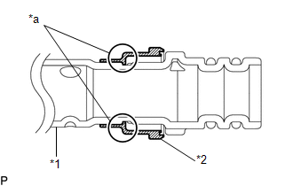
(3) Sufficiently apply compressor oil to 2 new O-rings and the fitting surfaces of the suction hose sub-assembly.
Compressor Oil:
ND-OIL 12 or equivalent
(4) Install the 2 O-rings to the suction hose sub-assembly.
NOTICE:
Keep the O-rings and O-ring fitting surfaces free from dirt and foreign matter.
| (5) Align the alignment marks and connect the suction pipe sub-assembly and suction hose sub-assembly. NOTICE: Connect the parts by holding the tubes, not the piping clamp. |
|
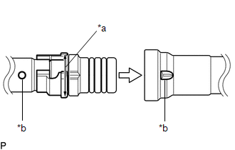
| (6) Securely insert the piping clamp to the point where the large diameter section of the piping clamp is covered by the suction pipe sub-assembly. NOTICE:
|
|
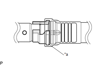
(b) for 2GR-FKS:
(1) Remove the vinyl tape from the No. 2 air conditioner tube and accessory assembly and suction hose sub-assembly.
| (2) Install a new piping clamp to the suction hose sub-assembly. NOTICE:
|
|
(3) Sufficiently apply compressor oil to 2 new O-rings and the fitting surfaces of the suction hose sub-assembly.
Compressor Oil:
ND-OIL 12 or equivalent
(4) Install the 2 O-rings to the suction hose sub-assembly.
NOTICE:
Keep the O-rings and O-ring fitting surfaces free from dirt and foreign matter.
| (5) Align the alignment marks and connect the No. 2 air conditioner tube and accessory assembly and suction hose sub-assembly. NOTICE: Connect the parts by holding the tubes, not the piping clamp. |
|
| (6) Securely insert the piping clamp to the point where the large diameter section of the piping clamp is covered by the No. 2 air conditioner tube and accessory assembly. NOTICE:
|
|
2. INSTALL PIPING CLAMP (for 2GR-FKS)
(a) Remove the vinyl tape from the air conditioner tube and accessory assembly and No. 2 air conditioner tube and accessory assembly.
(b) Sufficiently apply compressor oil to 2 new O-rings and the fitting surfaces of the No. 2 air conditioner tube and accessory assembly.
Compressor Oil:
ND-OIL 12 or equivalent
(c) Install the 2 O-rings to the air conditioner tube and accessory assembly.
(d) Install the air conditioner tube and accessory assembly to the No. 2 air conditioner tube and accessory assembly.
| (e) Install the piping clamp to the air conditioner tube and accessory assembly. NOTICE: Make sure that the piping clamp is installed securely with no gap. |
|
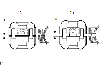
3. INSTALL PIPING CLAMP (for Air Conditioning Tube and Accessory Assembly Side)
Click here .gif)
4. CHARGE AIR CONDITIONING SYSTEM WITH REFRIGERANT
Click here
5. WARM UP ENGINE
Click here
6. INSPECT FOR REFRIGERANT LEAK
Click here
READ NEXT:
SEE MORE:
 Diagnostic Trouble Code Chart
DIAGNOSTIC TROUBLE CODE CHART Panoramic Moon Roof System
DTC No. Detection Item
Link B2341
Sensor (Motor) Failure
B2341 Sensor (Motor) Failure
B2342 Switch Failure
B2342 Switch Failure
B2343
Data List / Active Test
DATA LIST / ACTIVE TEST ACTIVE TEST HINT:
Using the Techstream to perform Active Tests allows relays, VSVs, actuators and other items to be operated without removing any parts. This non-intrusive functional inspection can be very useful because intermittent operation may be discovered before part
