Toyota Camry (XV70): License Plate Light Assembly
Components
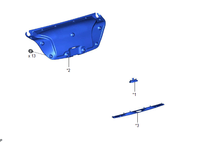
COMPONENTS
ILLUSTRATION
|
*1 | LICENSE PLATE LIGHT ASSEMBLY |
*2 | LUGGAGE COMPARTMENT DOOR COVER |
|
*3 | NO. 3 LUGGAGE COMPARTMENT DOOR OUTSIDE GARNISH |
- | - |
Removal
REMOVAL
CAUTION / NOTICE / HINT
HINT:
- Use the same procedure for the RH side and LH side.
- The following procedure is for the LH side.
PROCEDURE
1. REMOVE LUGGAGE COMPARTMENT DOOR COVER
Click here .gif)
2. REMOVE NO. 3 LUGGAGE COMPARTMENT DOOR OUTSIDE GARNISH
Click here
3. REMOVE LICENSE PLATE LIGHT ASSEMBLY
| (a) Disconnect the connector. |
|
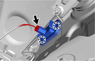
(b) Disengage the 2 claws to remove the license plate light assembly.
Inspection
INSPECTION
PROCEDURE
1. INSPECT LICENSE PLATE LIGHT ASSEMBLY
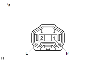
|
*a | Component without harness connected (License Plate Light Assembly) |
(a) Connect 4 dry-cell batteries (1.5 V) in series.
NOTICE:
Do not use rechargeable batteries as they may not output a voltage of 1.5 V.
(b) Apply 6 V batter voltage to the terminals of the connector and check that the license plate light illuminates.
OK:
|
Condition | Specified Condition |
|---|---|
|
Positive (+) lead from the batteries → Terminal 1 (B) Negative (-) lead from the batteries → Terminal 2 (E) |
License plate light illuminates |
If the result is not as specified, replace the license plate light assembly.
Installation
INSTALLATION
CAUTION / NOTICE / HINT
HINT:
- Use the same procedure for the RH side and LH side.
- The following procedure is for the LH side.
PROCEDURE
1. INSTALL LICENSE PLATE LIGHT ASSEMBLY
(a) Engage the 2 claws to install the license plate light assembly.
(b) Connect the connector.
2. INSTALL NO. 3 LUGGAGE COMPARTMENT DOOR OUTSIDE GARNISH
Click here .gif)
3. INSTALL LUGGAGE COMPARTMENT DOOR COVER
Click here
READ NEXT:
 Precaution
PRECAUTION PRECAUTION FOR DISCONNECTING CABLE FROM NEGATIVE BATTERY TERMINAL
NOTICE: When disconnecting the cable from the negative (-) battery terminal, initialize the following systems after the
Parts Location
PARTS LOCATION ILLUSTRATION
*A w/ Side Turn Signal Light
*B for A25A-FKS
*C for 2GR-FKS
- -
*1 HEADLIGHT ASSEMBLY LH
*2 HEADLIGHT ASSEMB
SEE MORE:
Check Bus 3 Line for Short to +B
DESCRIPTION There may be a short circuit between one of the CAN bus lines and +B when there is no resistance between terminal 6 (CA3H) of the central gateway ECU (network gateway ECU) and terminal 16 (BAT) of the DLC3, or terminal 21 (CA3L) of the central gateway ECU (network gateway ECU) and termin
Dtc Check / Clear
DTC CHECK / CLEAR CHECK FOR DTC (a) Connect the Techstream to the DLC3.
(b) Turn the ignition switch to ON. (c) Turn the Techstream on.
(d) Enter the following menus: Body Electrical / (desired system) / Trouble Codes. Body Electrical > Wiper > Trouble Codes Body Electrical > Main Bod
