Toyota Camry (XV70): Luggage Compartment Door Opener Outer Switch
Components
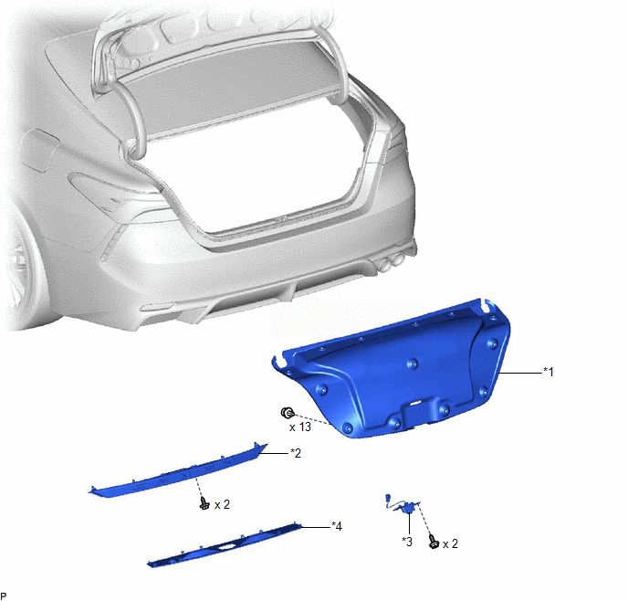
COMPONENTS
ILLUSTRATION
|
*1 | LUGGAGE COMPARTMENT DOOR COVER |
*2 | LUGGAGE COMPARTMENT DOOR OUTSIDE GARNISH SUB-ASSEMBLY |
|
*3 | LUGGAGE ELECTRICAL KEY SWITCH |
*4 | NO. 3 LUGGAGE COMPARTMENT DOOR OUTSIDE GARNISH |
Removal
REMOVAL
PROCEDURE
1. REMOVE LUGGAGE COMPARTMENT DOOR COVER
Click here
.gif)
2. REMOVE NO. 3 LUGGAGE COMPARTMENT DOOR OUTSIDE GARNISH
Click here
3. REMOVE LUGGAGE COMPARTMENT DOOR OUTSIDE GARNISH SUB-ASSEMBLY
Click here
4. REMOVE LUGGAGE ELECTRICAL KEY SWITCH
| (a) Disconnect the connector. |
|
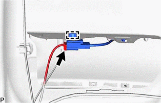
(b) Disengage the clamp.
| (c) Remove the 2 screws. |
|
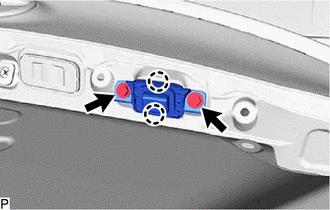
(d) Disengage the 2 claws to remove the luggage electrical key switch.
Inspection
INSPECTION
PROCEDURE
1. INSPECT LUGGAGE ELECTRICAL KEY SWITCH
(a) Check the switch.
| (1) Measure the resistance according to the value(s) in the table below. Standard Resistance:
If the result is not as specified, replace the luggage electrical key switch. |
|

Installation
INSTALLATION
PROCEDURE
1. INSTALL LUGGAGE ELECTRICAL KEY SWITCH
(a) Engage the 2 claws to install the luggage electrical key switch.
(b) Install the 2 screws.
(c) Engage the clamp.
(d) Connect the connector.
2. INSTALL LUGGAGE COMPARTMENT DOOR OUTSIDE GARNISH SUB-ASSEMBLY
Click here
.gif)
3. INSTALL NO. 3 LUGGAGE COMPARTMENT DOOR OUTSIDE GARNISH
Click here
4. INSTALL LUGGAGE COMPARTMENT DOOR COVER
Click here
READ NEXT:
 Precaution
PRECAUTION PRECAUTION FOR DISCONNECTING CABLE FROM NEGATIVE BATTERY TERMINAL
NOTICE: When disconnecting the cable from the negative (-) battery terminal, initialize the following systems after the
Parts Location
PARTS LOCATION ILLUSTRATION
*A w/ Smart Key System
- -
*1 LUGGAGE COMPARTMENT DOOR OPENING SWITCH ASSEMBLY
*2 DLC3
*3 MAIN BODY ECU (MULTIPLEX NE
SEE MORE:
Power Window Master Switch
ComponentsCOMPONENTS ILLUSTRATION
*1 MULTIPLEX NETWORK MASTER SWITCH ASSEMBLY
*2 MULTIPLEX NETWORK MASTER SWITCH ASSEMBLY WITH FRONT DOOR UPPER ARMREST BASE PANEL RemovalREMOVAL PROCEDURE
1. REMOVE MULTIPLEX NETWORK MASTER SWITCH ASSEMBLY WITH FRONT DOOR UPPER ARMREST B
Starter Signal Circuit
DESCRIPTION While the engine is being cranked, current flows from terminal STAR of the certification ECU (smart key ECU assembly) to the park/neutral position switch assembly and to terminal STA of the ECM (STA signal). WIRING DIAGRAM
Refer to DTC P061512. Click here
CAUTION / NOTICE / HINT
