Toyota Camry (XV70): Open in Bus 1 Main Bus Line
DESCRIPTION
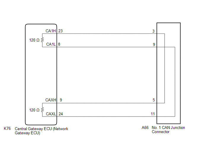
There may be an open circuit in one of the CAN main bus lines when the resistance between terminals 23 (CA1H) and 8 (CA1L) of the central gateway ECU (network gateway ECU) is 70 Ω or higher.
|
Symptom | Trouble Area |
|---|---|
|
Resistance between terminals 23 (CA1H) and 8 (CA1L) of the central gateway ECU (network gateway ECU) is 70 Ω or higher. |
|
This malfunction is not related to the lines of a CAN branch or to ECUs or sensors connected to a CAN branch.
WIRING DIAGRAM
w/ Parking Assist Monitor System or Panoramic View Monitor System w/ Rear View Monitor System
CAUTION / NOTICE / HINT
CAUTION:
When performing the confirmation driving pattern, obey all speed limits and traffic laws.
NOTICE:
- Because the order of diagnosis is important to allow correct diagnosis, make sure to begin troubleshooting using How to Proceed with Troubleshooting when CAN communication system related DTCs are output.
Click here
.gif)
- Before measuring the resistance of the CAN bus, turn the ignition switch off and leave the vehicle for 1 minute or more without operating the key or any switches, or opening or closing the doors. After that, disconnect the cable from the negative (-) battery terminal and leave the vehicle for 1 minute or more before measuring the resistance.
- After turning the ignition switch off, waiting time may be required before disconnecting the cable from the negative (-) battery terminal. Therefore, make sure to read the disconnecting the cable from the negative (-) battery terminal notices before proceeding with work.
Click here
- After performing repairs, perform the DTC check procedure and confirm that the DTCs are not output again.
DTC check procedure: Turn the ignition switch to ON and wait for 1 minute or more. Then operate the suspected malfunctioning system and drive the vehicle at 60 km/h (37 mph) or more for 5 minutes or more.
- After the repair, perform the CAN bus check and check that all the ECUs and sensors connected to the CAN communication system are displayed as normal.
Click here
HINT:
- Before disconnecting related connectors for inspection, push in on each connector body to check that the connector is not loose or disconnected.
- When a connector is disconnected, check that the terminals and connector body are not cracked, deformed or corroded.
PROCEDURE
|
1. | CHECK VEHICLE TYPE |
(a) Check vehicle type.
|
Result | Proceed to |
|---|---|
|
w/ Parking Assist Monitor System or Panoramic View Monitor System |
A |
| w/ Rear View Monitor System |
B |
| B |
.gif) | GO TO STEP 6 |
|
.gif)
| 2. |
CHECK FOR OPEN IN CAN MAIN BUS LINES (NO. 1 CAN JUNCTION CONNECTOR) |
(a) Disconnect the cable from the negative (-) battery terminal.
(b) Disconnect the A66 No. 1 CAN junction connector.
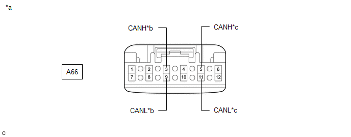
(c) Measure the resistance according to the value(s) in the table below.
|
*a | Front view of wire harness connector (to No. 1 CAN Junction Connector) |
*b | to Central Gateway ECU (Network Gateway ECU) |
|
*c | to No. 5 CAN Junction Connector |
- | - |
Standard Resistance:
|
Tester Connection | Condition |
Specified Condition | Connected to |
|---|---|---|---|
|
A66-3 (CANH) - A66-9 (CANL) |
Cable disconnected from negative (-) battery terminal |
108 to 132 Ω | Central gateway ECU (network gateway ECU) |
|
A66-5 (CANH) - A66-11 (CANL) |
Cable disconnected from negative (-) battery terminal |
108 to 132 Ω | No. 5 CAN junction connector |
|
Result | Proceed to |
|---|---|
|
OK | A |
|
NG (Line to central gateway ECU (network gateway ECU)) |
B |
| NG (Line to No. 5 CAN junction connector) |
C |
| A |
| REPLACE NO. 1 CAN JUNCTION CONNECTOR |
| C |
| GO TO STEP 4 |
|
| 3. |
CHECK FOR OPEN IN CAN MAIN BUS LINES (CENTRAL GATEWAY ECU (NETWORK GATEWAY ECU) - NO. 1 CAN JUNCTION CONNECTOR) |
(a) Reconnect the A66 No. 1 CAN junction connector.
(b) Disconnect the K76 central gateway ECU (network gateway ECU) connector.
| (c) Measure the resistance according to the value(s) in the table below. Standard Resistance:
|
|

| OK | | REPLACE CENTRAL GATEWAY ECU (NETWORK GATEWAY ECU)
|
| NG | | REPAIR OR REPLACE CAN MAIN BUS LINES OR CONNECTOR (CENTRAL GATEWAY ECU (NETWORK GATEWAY ECU) - NO. 1 CAN JUNCTION CONNECTOR) |
| 4. |
CHECK FOR OPEN IN CAN MAIN BUS LINES (NO. 5 CAN JUNCTION CONNECTOR) |
(a) Reconnect the A66 No. 1 CAN junction connector.
(b) Disconnect the R98 No. 5 CAN junction connector.
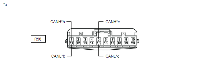
(c) Measure the resistance according to the value(s) in the table below.
|
*a | Front view of wire harness connector (to No. 5 CAN Junction Connector) |
*b | to Central Gateway ECU (Network Gateway ECU) |
|
*c | to No. 1 CAN Junction Connector |
- | - |
Standard Resistance:
|
Tester Connection | Condition |
Specified Condition | Connected to |
|---|---|---|---|
|
R98-1 (CANH) - R98-11 (CANL) |
Cable disconnected from negative (-) battery terminal |
108 to 132 Ω | Central gateway ECU (network gateway ECU) |
|
R98-5 (CANH) - R98-15 (CANL) |
Cable disconnected from negative (-) battery terminal |
108 to 132 Ω | No. 1 CAN junction connector |
|
Result | Proceed to |
|---|---|
|
OK | A |
|
NG (Line to No. 1 CAN junction connector) |
B |
| NG (Line to central gateway ECU (network gateway ECU)) |
C |
| A |
| REPLACE NO. 5 CAN JUNCTION CONNECTOR |
| B |
| REPAIR OR REPLACE CAN MAIN BUS LINES OR CONNECTOR (NO. 5 CAN JUNCTION CONNECTOR - NO. 1 CAN JUNCTION CONNECTOR) |
|
| 5. |
CHECK FOR OPEN IN CAN MAIN BUS LINES (CENTRAL GATEWAY ECU (NETWORK GATEWAY ECU) - NO. 5 CAN JUNCTION CONNECTOR) |
(a) Reconnect the R98 No. 5 CAN junction connector.
(b) Disconnect the K76 central gateway ECU (network gateway ECU) connector.
| (c) Measure the resistance according to the value(s) in the table below. Standard Resistance:
|
|
| OK | | REPLACE CENTRAL GATEWAY ECU (NETWORK GATEWAY ECU)
|
| NG | | REPAIR OR REPLACE CAN MAIN BUS LINES OR CONNECTOR (CENTRAL GATEWAY ECU (NETWORK GATEWAY ECU) - NO. 5 CAN JUNCTION CONNECTOR) |
| 6. |
CHECK FOR OPEN IN CAN MAIN BUS LINES (NO. 1 CAN JUNCTION CONNECTOR) |
(a) Disconnect the cable from the negative (-) battery terminal.
(b) Disconnect the A66 No. 1 CAN junction connector.
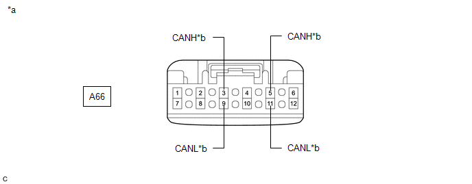
(c) Measure the resistance according to the value(s) in the table below.
|
*a | Front view of wire harness connector (to No. 1 CAN Junction Connector) |
*b | to Central Gateway ECU (Network Gateway ECU) |
Standard Resistance:
|
Tester Connection | Condition |
Specified Condition |
|---|---|---|
|
A66-3 (CANH) - A66-9 (CANL) |
Cable disconnected from negative (-) battery terminal |
108 to 132 Ω |
|
A66-5 (CANH) - A66-11 (CANL) |
Cable disconnected from negative (-) battery terminal |
108 to 132 Ω |
| OK | | REPLACE NO. 1 CAN JUNCTION CONNECTOR |
|
| 7. |
CHECK FOR OPEN IN CAN MAIN BUS LINES (CENTRAL GATEWAY ECU (NETWORK GATEWAY ECU) - NO. 1 CAN JUNCTION CONNECTOR) |
(a) Reconnect the A66 No. 1 CAN junction connector.
(b) Disconnect the K76 central gateway ECU (network gateway ECU) connector.
| (c) Measure the resistance according to the value(s) in the table below. Standard Resistance:
|
|
| OK | | REPLACE CENTRAL GATEWAY ECU (NETWORK GATEWAY ECU)
|
| NG | | REPAIR OR REPLACE CAN MAIN BUS LINES OR CONNECTOR (CENTRAL GATEWAY ECU (NETWORK GATEWAY ECU) - NO. 1 CAN JUNCTION CONNECTOR) |
READ NEXT:
 Check Bus 1 Lines for Short Circuit
DESCRIPTION There may be a short circuit between the CAN main bus lines and/or CAN branch lines when the resistance between terminals 23 (CA1H) and 8 (CA1L) of the central gateway ECU (network gateway
Check Bus 1 Line for Short to +B
DESCRIPTION There may be a short circuit between one of the CAN bus lines and +B when there is no resistance between terminal 23 (CA1H) of the central gateway ECU (network gateway ECU) and terminal 16
Check Bus 1 Line for Short to GND
DESCRIPTION There may be a short circuit between one of the CAN bus lines and GND when there is no resistance between terminal 23 (CA1H) of the central gateway ECU (network gateway ECU) and terminal 4
SEE MORE:
Installation
INSTALLATION PROCEDURE 1. INSTALL LUGGAGE COMPARTMENT DOOR OUTSIDE GARNISH SUB-ASSEMBLY
(a) Install 4 new clips to the luggage compartment door outside garnish sub-assembly.
(b) Engage the 4 clips as shown in the illustration.
Install in this Direction (c) Install the l
Brake Actuator Operation Sound is Loud during Initial Check
CAUTION / NOTICE / HINT NOTICE: After replacing the skid control ECU (brake actuator assembly), perform acceleration sensor zero point calibration and system information memorization.
Click here
PROCEDURE
1.
PERFORM ROAD TEST (a) After turning the ignition switch to ON, compare
