Toyota Camry (XV70): Parking Brake Switch
Components
COMPONENTS
ILLUSTRATION
|
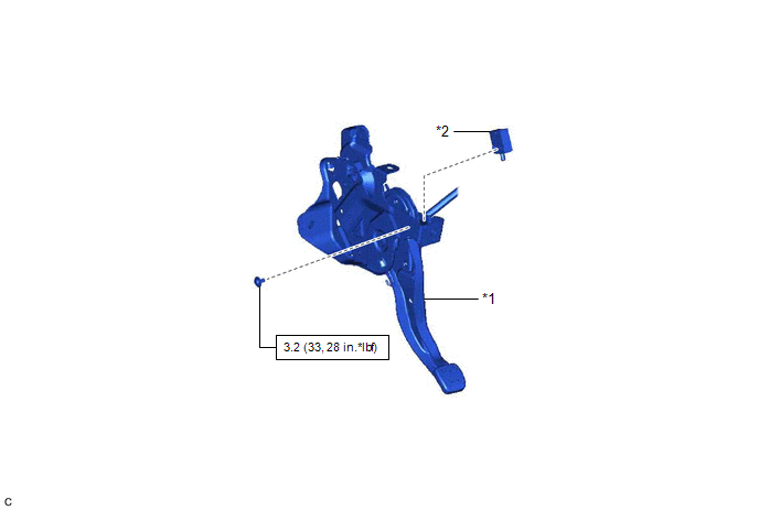
*1 | PARKING BRAKE PEDAL ASSEMBLY |
*2 | PARKING BRAKE SWITCH ASSEMBLY |
.png) |
N*m (kgf*cm, ft.*lbf): Specified torque |
- | - |
Removal
REMOVAL
CAUTION / NOTICE / HINT
The necessary procedures (adjustment, calibration, initialization, or registration) that must be performed after parts are removed and installed, or replaced during parking brake switch assembly removal/installation are shown below.
Necessary Procedures After Parts Removed/Installed/Replaced|
Replaced Part or Performed Procedure |
Necessary Procedure | Effect/Inoperative Function when Necessary Procedure not Performed |
Link |
|---|---|---|---|
|
*1: When performing learning using the Techstream.
Click here | |||
|
Disconnect cable from negative battery terminal |
Perform steering sensor zero point calibration |
Lane Tracing Assist System |
|
|
Pre-collision system | |||
|
Parking Support Brake System*1 | |||
|
Memorize steering angle neutral point |
Parking assist monitor system |
| |
|
Panoramic view monitor system |
| ||
PROCEDURE
1. SEPARATE PARKING BRAKE PEDAL ASSEMBLY
Click here
.gif)
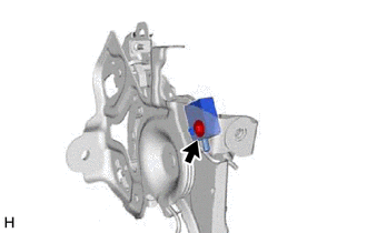
2. REMOVE PARKING BRAKE SWITCH ASSEMBLY
| (a) Remove the screw and parking brake switch assembly from the parking brake pedal assembly. |
|
Inspection
INSPECTION
PROCEDURE
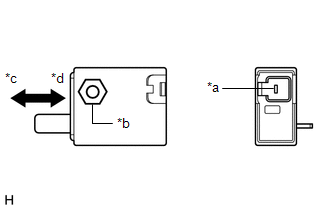
1. INSPECT PARKING BRAKE SWITCH ASSEMBLY
| (a) Measure the resistance between the connector terminal and the nut inside the parking brake switch assembly. Standard Resistance
If the result is not as specified, replace the parking brake switch assembly. |
|
Installation
INSTALLATION
PROCEDURE
1. INSTALL PARKING BRAKE SWITCH ASSEMBLY
(a) Install the parking brake switch assembly to the parking brake pedal assembly with the screw.
Torque:
3.2 N
READ NEXT:
 Problem Symptoms Table
PROBLEM SYMPTOMS TABLE HINT: Use the table below to help determine the cause of problem symptoms. If multiple suspected areas are listed, the potential causes of the symptoms are listed in order of pr
Adjustment
ADJUSTMENT PROCEDURE 1. INSPECT PARKING BRAKE PEDAL TRAVEL
(a) Completely release the parking brake pedal assembly. (b) Fully depress the parking brake pedal assembly to engage the parking brake.
SEE MORE:
Removal
REMOVAL CAUTION / NOTICE / HINT
The necessary procedures (adjustment, calibration, initialization, or registration) that must be performed after parts are replaced during forward recognition camera removal/installation are shown below. Necessary Procedure After Parts Removed/Installed/Replaced
Inspection
INSPECTION PROCEDURE 1. INSPECT NAVIGATION ANTENNA ASSEMBLY (w/o Manual (SOS) Switch)
(a) Check that the navigation antenna assembly cable is properly installed and does not have any sharp bends, pinching or loose connections.
(b) Current consumption check:
(1) Measure the current consumpt
