Toyota Camry (XV70): Inspection
INSPECTION
PROCEDURE
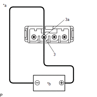
1. INSPECT NAVIGATION ANTENNA ASSEMBLY (w/o Manual (SOS) Switch)
(a) Check that the navigation antenna assembly cable is properly installed and does not have any sharp bends, pinching or loose connections.
(b) Current consumption check:
| (1) Measure the current consumption according to the value(s) in the table below. Standard Current:
NOTICE: Do not apply 6 V or more between terminals 3 and 3a. HINT: If a stable power supply is not available, connect 4 nickel-metal hydride batteries (1.2 V each) or equivalent in series. |
|
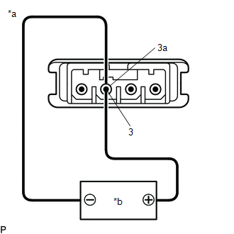
2. INSPECT NAVIGATION ANTENNA ASSEMBLY (w/ Manual (SOS) Switch)
(a) Check that the navigation antenna assembly cable is properly installed and does not have any sharp bends, pinching or loose connections.
(b) Current consumption check: (GPS)
| (1) Measure the current consumption according to the value(s) in the table below. Standard Current:
NOTICE: Do not apply 6 V or more between terminals 3 and 3a. HINT: If a stable power supply is not available, connect 4 nickel-metal hydride batteries (1.2 V each) or equivalent in series. |
|
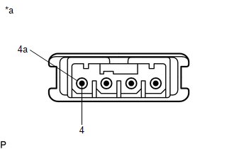
(c) Resistance check: (Telephone Sub)
| (1) Measure the resistance according to the value(s) in the table below. Standard Resistance:
|
|
READ NEXT:
 Installation
INSTALLATION PROCEDURE 1. INSTALL NAVIGATION ANTENNA BRACKET
2. INSTALL NAVIGATION ANTENNA ASSEMBLY (a) Engage the 6 guides and 2 claws to install the navigation antenna assembly as shown in the ill
Components
COMPONENTS ILLUSTRATION
*A for 7 Inch Display
*B for 9 Inch Display
*C w/o Manual (SOS) Switch
*D w/ Manual (SOS) Switch
*1 CENTER INSTRUMENT CLUSTER FI
SEE MORE:
XM Tuner Antenna Disconnected (B15FE,B15FF)
DESCRIPTION These DTCs are stored when a malfunction occurs in the roof antenna assembly which is connected to the radio and display receiver assembly.
DTC No. Detection Item
DTC Detection Condition Trouble Area
B15FE XM Tuner Antenna Disconnected
The roof antenna asse
Parts Location
PARTS LOCATION ILLUSTRATION
*1 INNER REAR VIEW MIRROR ASSEMBLY
- GARAGE DOOR OPENER *2
INSTRUMENT PANEL JUNCTION BLOCK ASSEMBLY - ECU-DCC NO. 2 FUSE
- ECU-IG1 NO. 3 FUSE
