
Toyota Camry (XV70): Installation
INSTALLATION
PROCEDURE
1. INSTALL NAVIGATION ANTENNA BRACKET
2. INSTALL NAVIGATION ANTENNA ASSEMBLY
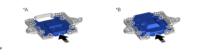
(a) Engage the 6 guides and 2 claws to install the navigation antenna assembly as shown in the illustration.
|
*A | w/o Manual (SOS) Switch |
*B | w/ Manual (SOS) Switch |
.png) |
Install in this Direction |
- | - |
3. INSTALL NAVIGATION ANTENNA ASSEMBLY WITH BRACKET
(a) Install the navigation antenna assembly with bracket with the 2 screws.
(b) Engage the 2 claws.
(c) Connect the connector.
4. INSTALL NO. 3 HEATER TO REGISTER DUCT SUB-ASSEMBLY
Click here .gif)
5. INSTALL INSTRUMENT PANEL SAFETY PAD SUB-ASSEMBLY
Click here
READ NEXT:
 Components
COMPONENTS ILLUSTRATION
*A for 7 Inch Display
*B for 9 Inch Display
*C w/o Manual (SOS) Switch
*D w/ Manual (SOS) Switch
*1 CENTER INSTRUMENT CLUSTER FI
Removal
REMOVAL PROCEDURE 1. PRECAUTION
NOTICE:
When replacing the radio and display receiver assembly or navigation ECU, always replace it with a new one. If a radio and display receiver assembly or na
SEE MORE:
Data List / Active Test
DATA LIST / ACTIVE TEST DATA LIST NOTICE:
In the table below, the values listed under "Normal Condition" are reference values. Do not depend solely on these reference values when deciding whether a part is faulty or not.
HINT: Using the Techstream to read the Data List allows the values or state
Parts Location
PARTS LOCATION ILLUSTRATION
*1 ROOF CONSOLE BOX SUB-ASSEMBLY
*2 TELEPHONE MICROPHONE ASSEMBLY
*3 ENGINE ROOM RELAY BLOCK AND JUNCTION BLOCK ASSEMBLY
- TV FUSE (for 9 Inch Display Type)
*4 INSTRUMENT PANEL JUNCTION BLOCK ASSEMBLY
- ECU-ACC FUSE - ECU-DCC
© 2023-2026 Copyright www.tocamry.com
