Toyota Camry (XV70): Parts Location
PARTS LOCATION
ILLUSTRATION
|
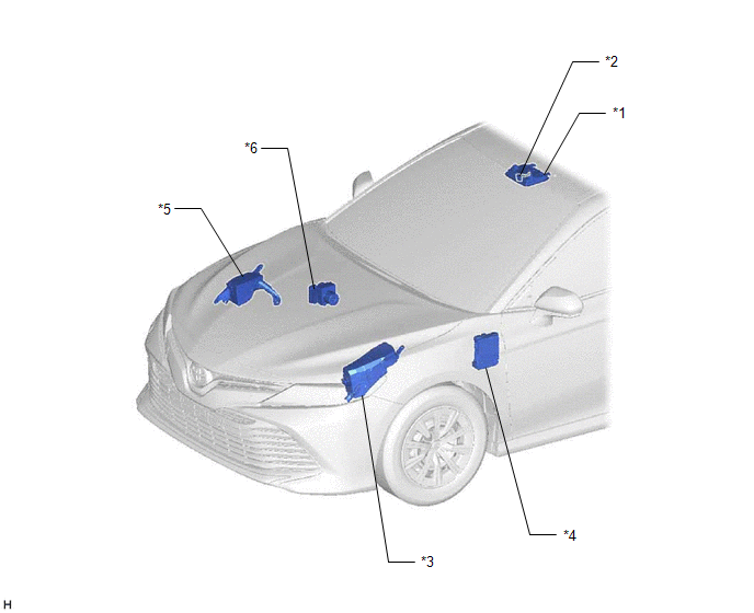
*1 | ROOF CONSOLE BOX SUB-ASSEMBLY |
*2 | TELEPHONE MICROPHONE ASSEMBLY |
|
*3 | ENGINE ROOM RELAY BLOCK AND JUNCTION BLOCK ASSEMBLY - TV FUSE (for 9 Inch Display Type) |
*4 | INSTRUMENT PANEL JUNCTION BLOCK ASSEMBLY - ECU-ACC FUSE - ECU-DCC NO. 2 FUSE - ECU-IG1 NO. 4 FUSE - ECU-IG2 NO. 3 FUSE (w/ Manual (SOS) Switch) - DCM FUSE (w/ Manual (SOS) Switch) - PANEL FUSE - METER-IG2 FUSE - RADIO FUSE (for 7 Inch Display Type) |
|
*5 | NO. 2 ENGINE ROOM RELAY BLOCK AND JUNCTION BLOCK ASSEMBLY - AMP NO. 1 FUSE (for 9 Speakers) - AMP NO. 2 FUSE (for 9 Speakers) |
*6 | SKID CONTROL ECU (BRAKE ACTUATOR ASSEMBLY) (for Electric Parking Brake System) |
ILLUSTRATION
|
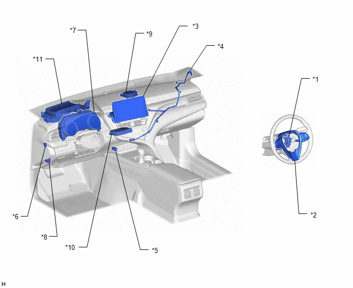
*1 | SPIRAL CABLE SUB-ASSEMBLY |
*2 | STEERING PAD SWITCH ASSEMBLY |
|
*3 | RADIO AND DISPLAY RECEIVER ASSEMBLY |
*4 | ANTENNA CORD SUB-ASSEMBLY (for Front Side) |
|
*5 | NO. 1 STEREO JACK ADAPTER ASSEMBLY |
*6 | PARKING BRAKE SWITCH ASSEMBLY (for Parking Brake Pedal Type) |
|
*7 | COMBINATION METER ASSEMBLY |
*8 | DLC3 |
|
*9 | NAVIGATION ANTENNA ASSEMBLY (w/ Navigation Antenna Assembly) - GPS | *10 |
DCM (TELEMATICS TRANSCEIVER) (w/ Manual (SOS) Switch) |
|
*11 | HEADUP DISPLAY (METER MIRROR SUB-ASSEMBLY) (w/ Headup Display System) |
- | - |
ILLUSTRATION
for 6 Speakers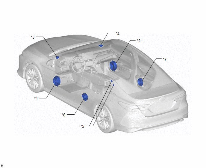
|
*1 | FRONT NO. 1 SPEAKER ASSEMBLY LH |
*2 | FRONT NO. 1 SPEAKER ASSEMBLY RH |
|
*3 | FRONT NO. 2 SPEAKER ASSEMBLY LH |
*4 | FRONT NO. 2 SPEAKER ASSEMBLY RH |
|
*5 | RADIO SETTING CONDENSER |
*6 | REAR SPEAKER ASSEMBLY LH |
|
*7 | REAR SPEAKER ASSEMBLY RH |
- | - |
ILLUSTRATION
for 9 Speakers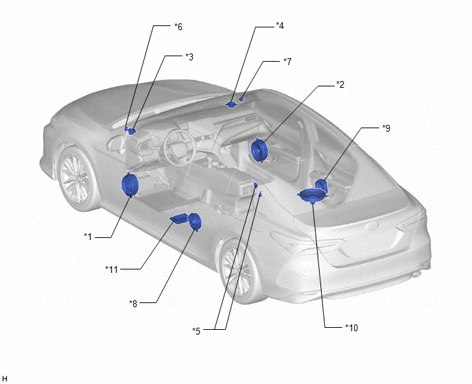
|
*1 | FRONT NO. 1 SPEAKER ASSEMBLY LH |
*2 | FRONT NO. 1 SPEAKER ASSEMBLY RH |
|
*3 | FRONT NO. 2 SPEAKER ASSEMBLY LH |
*4 | FRONT NO. 1 SPEAKER ASSEMBLY RH |
|
*5 | RADIO SETTING CONDENSER |
*6 | FRONT NO. 3 SPEAKER ASSEMBLY LH |
|
*7 | FRONT NO. 3 SPEAKER ASSEMBLY RH |
*8 | REAR SPEAKER ASSEMBLY LH |
|
*9 | REAR SPEAKER ASSEMBLY RH |
*10 | REAR STEREO COMPONENT SPEAKER ASSEMBLY |
|
*11 | STEREO COMPONENT AMPLIFIER ASSEMBLY |
- | - |
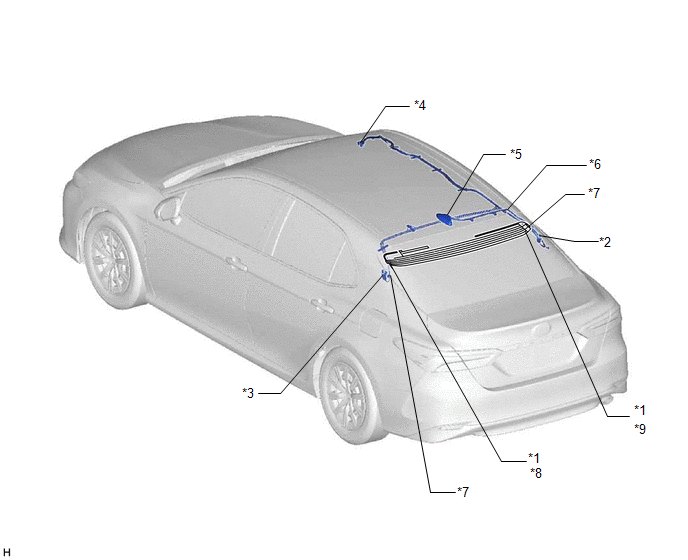
ILLUSTRATION
|
*1 | WINDOW GLASS ANTENNA WIRE |
*2 | NO. 1 AMPLIFIER ANTENNA ASSEMBLY |
|
*3 | NO. 2 AMPLIFIER ANTENNA ASSEMBLY |
*4 | NO. 2 ANTENNA CORD SUB-ASSEMBLY |
|
*5 | ROOF ANTENNA ASSEMBLY (w/ SXM Function) - SiriusXM | *6 |
NO. 5 ANTENNA CORD SUB-ASSEMBLY (w/ SXM Function) |
|
*7 | ANTENNA CORD SUB-ASSEMBLY (for Rear Side) |
*8 | - FM Sub |
|
*9 | - FM Main - AM |
- | - |
READ NEXT:
 System Description
SYSTEM DESCRIPTION USB AUDIO SYSTEM FUNCTION OUTLINE
(a) The No. 1 stereo jack adapter assembly is equipped with a USB connector. Connecting a USB device or "iPod" to the No. 1 stereo jack adapter a
How To Proceed With Troubleshooting
CAUTION / NOTICE / HINT
HINT:
Use the following procedure to troubleshoot the audio and visual system.
*: Use the Techstream.
PROCEDURE
1. VEHICLE BROUGHT TO WORKSHOP
Operation Check
OPERATION CHECK STORAGE CHECK
NOTICE:
When replacing the radio and display receiver assembly, always replace it with a new one. If a radio and display receiver assembly which was installed to an
SEE MORE:
Left Rear Wheel Speed Sensor Circuit Short to Battery (C050C12)
DESCRIPTION Each speed sensor detects wheel speed and sends signals to the skid control ECU (brake actuator assembly). These signals are used by the ABS control.
The speed sensor detects the magnetic fields of the speed sensor rotor as it rotates and outputs a pulse signal.
The frequency of the
Diagnosis System
DIAGNOSIS SYSTEM DIAGNOSIS FUNCTION (a) The diagnosis function turns off the cruise control indicator, illuminates the master warning light and displays a warning message when a malfunction is detected. When a malfunction is detected in the dynamic radar cruise control system, DTCs are stored in the
