Toyota Camry (XV70): Parts Location
Toyota Camry Repair Manual XV70 (2018-2024) / Engine, Hybrid System / 2gr-fks (cooling) / Cooling Fan System / Parts Location
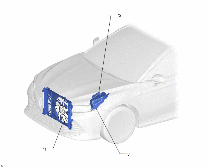
PARTS LOCATION
ILLUSTRATION
|
*1 | FAN WITH MOTOR ASSEMBLY - COOLING FAN MOTOR - COOLING FAN ECU | *2 |
ECM |
| *3 |
ENGINE ROOM RELAY BLOCK AND JUNCTION BLOCK ASSEMBLY - EFI-MAIN NO. 1 RELAY |
- | - |
READ NEXT:
 System Diagram
SYSTEM DIAGRAM
Problem Symptoms Table
PROBLEM SYMPTOMS TABLE
HINT:
Use the table below to help determine the cause of problem symptoms. If multiple suspected areas are listed, the potential causes of the symptoms are listed in order
On-vehicle Inspection
ON-VEHICLE INSPECTION PROCEDURE
1. INSPECT COOLING FAN SYSTEM CAUTION: To prevent injury due to contact with an operating cooling fan, keep your hands and clothing away from the cooling fan when ins
SEE MORE:
Removal
REMOVAL CAUTION / NOTICE / HINT
The necessary procedures (adjustment, calibration, initialization or registration) that must be performed after parts are removed and installed, or replaced during fuel injector assembly removal/installation are shown below. Necessary Procedures After Parts Removed/
Seat belt instructions
for Canadian owners
(in French)
The following is a French explanation of seat belt instructions
extracted from the seat belt section in this manual.
See the seat belt section for more detailed seat belt instructions in
English.
Utilisation correcte des ceintures de sécurité
Déroulez la sangle diagonale
de telle sorte
© 2023-2026 Copyright www.tocamry.com
