Toyota Camry (XV70): Parts Location
Toyota Camry Repair Manual XV70 (2018-2024) / Engine, Hybrid System / Cruise Control / Front Radar Sensor System / Parts Location
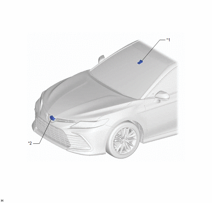
PARTS LOCATION
ILLUSTRATION
|
*1 | FORWARD RECOGNITION CAMERA |
*2 | MILLIMETER WAVE RADAR SENSOR ASSEMBLY |
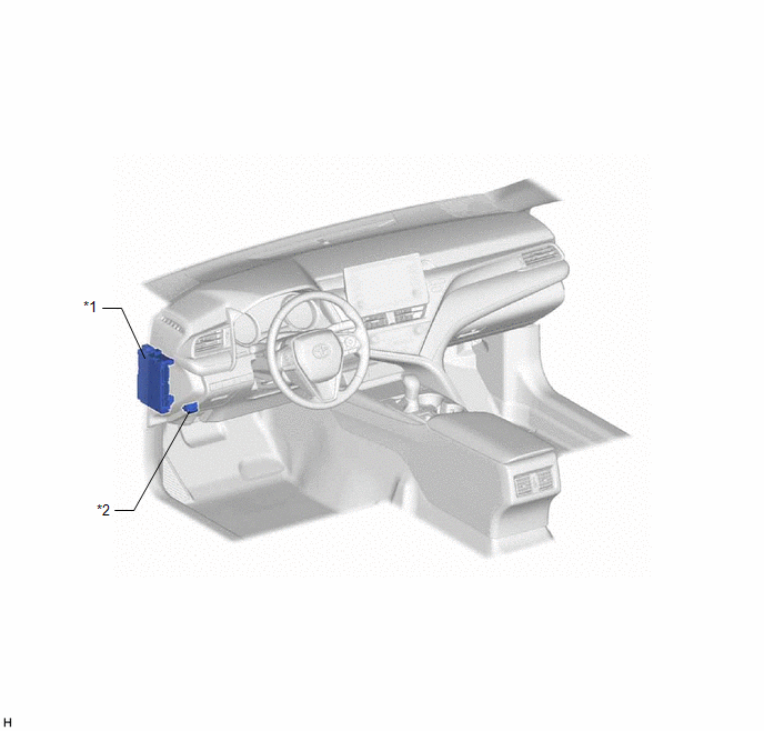
ILLUSTRATION
|
*1 | INSTRUMENT PANEL JUNCTION BLOCK ASSEMBLY - ECU-IG1 NO. 3 FUSE | *2 |
DLC3 |
READ NEXT:
 System Diagram
SYSTEM DIAGRAM
How To Proceed With Troubleshooting
CAUTION / NOTICE / HINT
HINT:
Before performing troubleshooting for the front radar sensor system, perform troubleshooting for the pre-collision system.
Click here
*: Use the Techstream.
Utility
UTILITY Front Beam Axis Adjustment HINT:
Front Beam Axis Adjustment is used to calibrate the beam axis of millimeter wave radar sensor assembly.
(a) Perform Front Beam Axis Adjustment according to
SEE MORE:
Removal
REMOVAL CAUTION / NOTICE / HINT
The necessary procedures (adjustment, calibration, initialization or registration) that must be performed after parts are removed and installed, or replaced during radiator assembly removal/installation are shown below. Necessary Procedures After Parts Removed/Insta
Disassembly
DISASSEMBLY PROCEDURE 1. REMOVE NO. 2 LUGGAGE COMPARTMENT DOOR NAME PLATE
Click here
2. REMOVE LUGGAGE COMPARTMENT DOOR OUTSIDE GARNISH PROTECTOR
(a) Remove the luggage compartment door outside garnish protector from the luggage compartment door outside garnish.
© 2023-2026 Copyright www.tocamry.com
