Toyota Camry (XV70): System Diagram
Toyota Camry Repair Manual XV70 (2018-2024) / Engine, Hybrid System / Cruise Control / Front Radar Sensor System / System Diagram
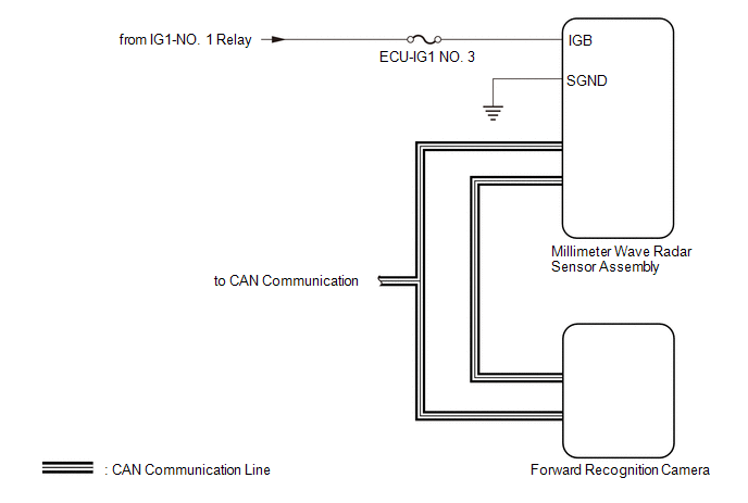
SYSTEM DIAGRAM
READ NEXT:
 How To Proceed With Troubleshooting
CAUTION / NOTICE / HINT
HINT:
Before performing troubleshooting for the front radar sensor system, perform troubleshooting for the pre-collision system.
Click here
*: Use the Techstream.
Utility
UTILITY Front Beam Axis Adjustment HINT:
Front Beam Axis Adjustment is used to calibrate the beam axis of millimeter wave radar sensor assembly.
(a) Perform Front Beam Axis Adjustment according to
Problem Symptoms Table
PROBLEM SYMPTOMS TABLE
HINT:
Use the table below to help determine the cause of problem symptoms. If multiple suspected areas are listed, the potential causes of the symptoms are listed in order
SEE MORE:
Fail-safe Chart
FAIL-SAFE CHART PROTECTION FUNCTION (a) The windshield wiper motor assembly operates the following protection functions if it detects an abnormal condition, in order to protect the wiper and washer system.
Item Protection Content
Conditions to Return to Normal Condition
Overh
Cruise Main Indicator Light Circuit
DESCRIPTION When the dynamic radar cruise control system is turned on using the cruise control main switch, the cruise control indicator (vehicle-to-vehicle distance control mode) illuminates. The ECM uses this and other indicators to indicate the status (presence or absence of a preceding vehicle,
© 2023-2026 Copyright www.tocamry.com
