Toyota Camry (XV70): Parts Location
Toyota Camry Repair Manual XV70 (2018-2024) / Engine, Hybrid System / Cruise Control / Lane Tracing Assist System / Parts Location
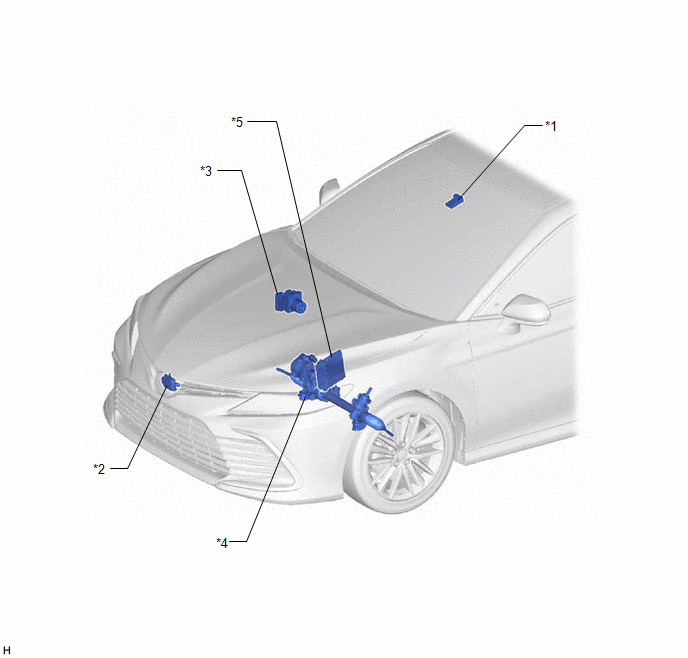
PARTS LOCATION
ILLUSTRATION
|
*1 | FORWARD RECOGNITION CAMERA |
*2 | MILLIMETER WAVE RADAR SENSOR ASSEMBLY |
|
*3 | SKID CONTROL ECU (BRAKE ACTUATOR ASSEMBLY) |
*4 | POWER STEERING ECU (RACK AND PINION POWER STEERING GEAR ASSEMBLY) |
|
*5 | ECM |
- | - |
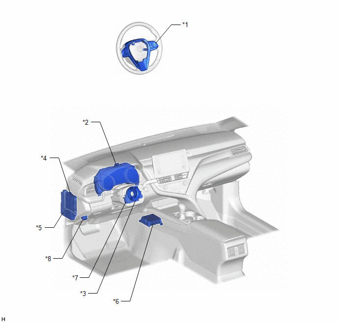
ILLUSTRATION
|
*1 | STEERING PAD SWITCH ASSEMBLY |
*2 | COMBINATION METER ASSEMBLY |
|
*3 | SPIRAL CABLE SUB-ASSEMBLY |
*4 | MAIN BODY ECU (MULTIPLEX NETWORK BODY ECU) |
|
*5 | INSTRUMENT PANEL JUNCTION BLOCK ASSEMBLY - ECU-IG1 NO. 3 FUSE |
*6 | AIRBAG SENSOR ASSEMBLY |
|
*7 | STEERING SENSOR |
*8 | DLC3 |
READ NEXT:
 System Diagram
SYSTEM DIAGRAM
How To Proceed With Troubleshooting
CAUTION / NOTICE / HINT
HINT:
Use the following procedure to troubleshoot the lane tracing assist system.
*: Use the Techstream.
PROCEDURE
1. VEHICLE BROUGHT TO WORKSHOP
Customize Parameters
CUSTOMIZE PARAMETERS CUSTOMIZE LANE TRACING ASSIST SYSTEM
NOTICE: Record the settings when the vehicle is brought to the workshop so they can be restored.
(a) Customizing with the multi-informatio
SEE MORE:
Reassembly
REASSEMBLY CAUTION / NOTICE / HINT PROCEDURE
1. TEMPORARILY TIGHTEN FRONT DISC BRAKE BLEEDER PLUG (a) Temporarily install the front disc brake bleeder plug to the front disc brake cylinder.
HINT: Fully tighten the front disc brake bleeder plug after bleeding the system.
2. INSTALL FRONT DISC B
Components
COMPONENTS ILLUSTRATION
*1 FRONT CENTER UPPER SUSPENSION BRACE SUB-ASSEMBLY
- -
Tightening torque for "Major areas involving basic vehicle performance such as moving/turning/stopping" : N*m (kgf*cm, ft.*lbf)
N*m (kgf*cm, ft.*lbf): Specified torque
© 2023-2026 Copyright www.tocamry.com
