Toyota Camry (XV70): Parts Location
PARTS LOCATION
ILLUSTRATION
|
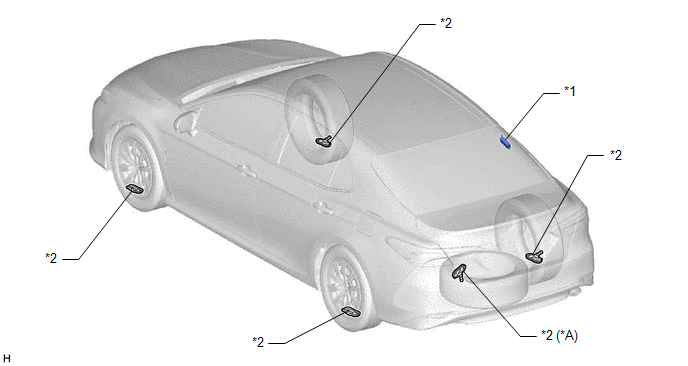
*A | w/ Full Size Spare Tire |
- | - |
|
*1 | TIRE PRESSURE WARNING ECU AND RECEIVER |
*2 | TIRE PRESSURE WARNING VALVE AND TRANSMITTER |
ILLUSTRATION
|
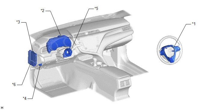
*1 | STEERING PAD SWITCH ASSEMBLY |
*2 | COMBINATION METER ASSEMBLY - TIRE PRESSURE WARNING LIGHT - MULTI-INFORMATION DISPLAY |
|
*3 | MAIN BODY ECU (MULTIPLEX NETWORK BODY ECU) |
*4 | DLC3 |
|
*5 | SPIRAL CABLE SUB-ASSEMBLY |
*6 | INSTRUMENT PANEL JUNCTION BLOCK ASSEMBLY - ECU-IG1 NO. 4 FUSE - ECU-B NO. 2 FUSE - ECU-DCC NO. 2 FUSE |
ILLUSTRATION
|
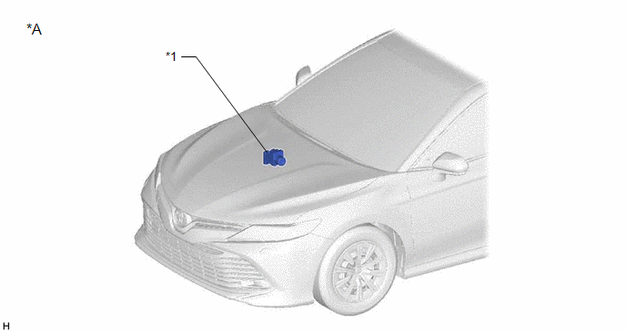
*A | w/ Tire Inflation Pressure Display Function |
- | - |
|
*1 | SKID CONTROL ECU (BRAKE ACTUATOR ASSEMBLY) |
- | - |
READ NEXT:
 System Diagram
SYSTEM DIAGRAM
HINT: Each tire pressure warning valve and transmitter sends its transmitter ID, temperature and tire pressure information to the tire pressure warning ECU and receiver.
Tra
How To Proceed With Troubleshooting
CAUTION / NOTICE / HINT
HINT:
Use the following procedure to troubleshoot the tire pressure warning system.
Make sure that the wireless door lock control system has exited diagnostic mode b
Operation Check
OPERATION CHECK CHECK TIRE PRESSURE WARNING SYSTEM FUNCTION
(a) Using the Data List, check that the current tire pressure is normal.
Click here
(1) Slowly reduce the tire pressure of the
SEE MORE:
Knock Sensor 1 Bank 1 or Single Sensor Circuit Short to Battery or Open (P032515,P033015)
DESCRIPTION Refer to DTC P032511. Click here
HINT: When DTC P032515 or P033015 is stored, the ECM enters fail-safe mode. During fail-safe mode, the ignition timing is delayed to its maximum retardation. Fail-safe mode continues until the engine switch is turned off.
DTC No. Detection Ite
Disassembly
DISASSEMBLY PROCEDURE 1. REMOVE GENERATOR PULLEY CAP
(a) Using a screwdriver, remove the generator pulley cap from the generator pulley with clutch.
NOTICE:
Do not reuse the generator pulley cap.
If the generator pulley cap is removed, replace the generator pulley cap and generat
© 2023-2026 Copyright www.tocamry.com
