Toyota Camry (XV70): System Diagram
SYSTEM DIAGRAM
HINT:
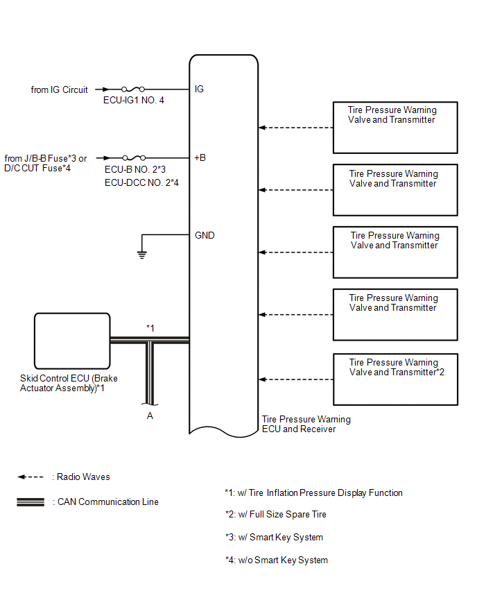
Each tire pressure warning valve and transmitter sends its transmitter ID, temperature and tire pressure information to the tire pressure warning ECU and receiver.
|
Transmitting ECU (Transmitter) |
Receiving ECU | Signal |
Communication Method |
|---|---|---|---|
|
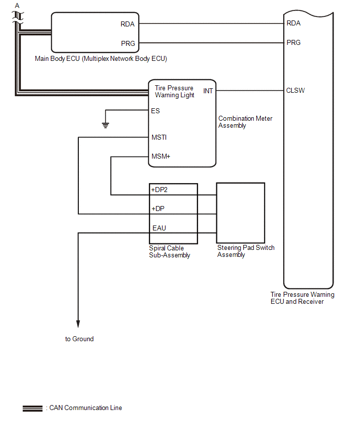
Combination Meter Assembly |
Main Body ECU (Multiplex Network Body ECU) |
Vehicle speed signal |
CAN communication line |
|
Main Body ECU (Multiplex Network Body ECU) |
Combination Meter Assembly |
Tire pressure warning light signal |
CAN communication line |
|
Skid Control ECU (Brake Actuator Assembly) |
Tire Pressure Warning ECU and Receiver |
Speed sensor signal* |
CAN communication line |
- *: w/ Tire Inflation Pressure Display Function
READ NEXT:
 How To Proceed With Troubleshooting
CAUTION / NOTICE / HINT
HINT:
Use the following procedure to troubleshoot the tire pressure warning system.
Make sure that the wireless door lock control system has exited diagnostic mode b
Operation Check
OPERATION CHECK CHECK TIRE PRESSURE WARNING SYSTEM FUNCTION
(a) Using the Data List, check that the current tire pressure is normal.
Click here
(1) Slowly reduce the tire pressure of the
Registration
REGISTRATION PROCEDURE 1. BEFORE REGISTRATION
NOTICE:
The transmitter ID is written on the tire pressure warning valve and transmitter. It is not possible to read the transmitter ID after instal
SEE MORE:
Components
COMPONENTS ILLUSTRATION
*1 FRONT FENDER TO COWL SIDE SEAL
*2 NO. 1 WINDSHIELD OUTSIDE MOULDING CLIP
*3 NO. 3 WINDSHIELD OUTSIDE MOULDING CLIP
*4 WINDSHIELD OUTSIDE MOULDING
*5 WINDSHIELD GLASS SUB-ASSEMBLY
- -
● Non-reu
System Diagram
SYSTEM DIAGRAM
*1 Throttle Body with Motor Assembly
*2 Intake Air Control Valve (for ACIS)
*3 Intake Air Control Valve Actuator (for ACIS)
*4 ECM
*5 Vacuum Switching Valve (for ACIS)
- -
*a Engine Speed Signal
*b from Vacuum P
© 2023-2026 Copyright www.tocamry.com
