
Toyota Camry (XV70): Parts Location
Toyota Camry Repair Manual XV70 (2018-2024) / Vehicle Exterior / Window / Glass / Window Defogger System / Parts Location
PARTS LOCATION
ILLUSTRATION
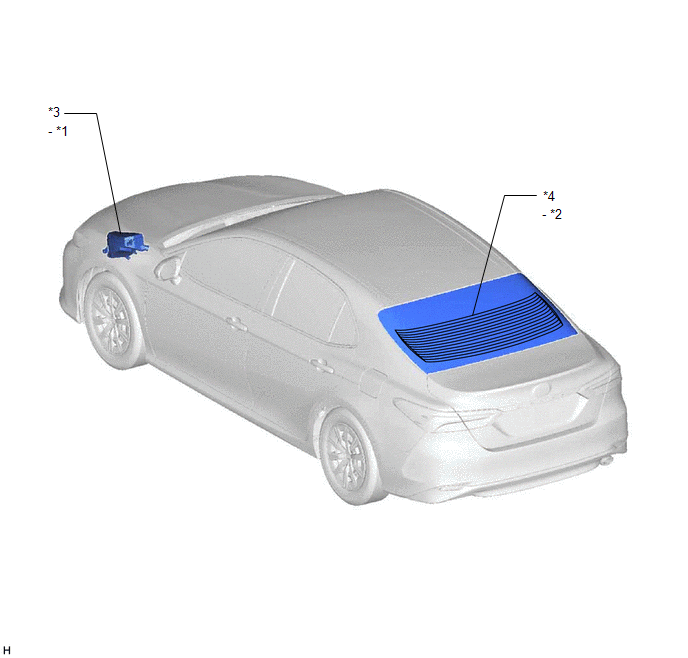
|
*1 | DEF RELAY |
*2 | REAR WINDOW DEFOGGER WIRE |
|
*3 | ENGINE ROOM RELAY BLOCK AND JUNCTION BLOCK ASSEMBLY - DEF FUSE | *4 |
BACK WINDOW GLASS |
ILLUSTRATION
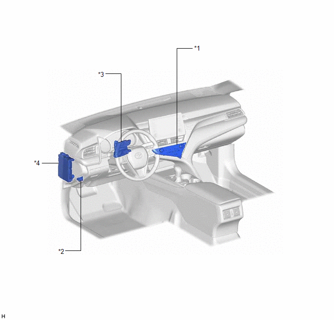
|
*1 | REAR WINDOW DEFOGGER SWITCH (AIR CONDITIONING CONTROL ASSEMBLY) |
*2 | DLC3 |
|
*3 | AIR CONDITIONING AMPLIFIER ASSEMBLY |
*4 | INSTRUMENT PANEL JUNCTION BLOCK ASSEMBLY - ECU-IG1 NO. 3 FUSE |
READ NEXT:
 System Diagram
SYSTEM DIAGRAM
Communication Table
Transmitter Receiver
Signal Communication Method
Rear Window Defogger Switch (Air Conditioning Control Assembly)
Air Conditionin
System Description
SYSTEM DESCRIPTION GENERAL (a) The rear window defogger wire (back window glass) is attached to the inside of the rear window and defogs the window surface quickly when the rear window defogger switch
How To Proceed With Troubleshooting
CAUTION / NOTICE / HINT
HINT:
Use the following procedure to troubleshoot the window defogger system.
*: Use the Techstream.
PROCEDURE
1. VEHICLE BROUGHT TO WORKSHOP
SEE MORE:
Message Not Displayed on Multi-information Display When AUTO Function Set to ON/OFF
DESCRIPTION When the AUTO function is set to ON/OFF, a message is displayed on the multi-information display in the combination meter assembly. WIRING DIAGRAM
PROCEDURE
1.
CHECK OPERATION OF AUTO FUNCTION (a) Check that the AUTO function operates when the operating conditions are me
Dtc Check / Clear
DTC CHECK / CLEAR CHECK DTC AND FREEZE FRAME DATA (USING TECHSTREAM)
(a) Turn the ignition switch off. (b) Connect the Techstream to the DLC3.
(c) Turn the ignition switch to ON. (d) Turn the Techstream on.
(e) Enter the following menus: Chassis / Brake/EPB / Trouble Codes. Chassis > Brake
© 2023-2026 Copyright www.tocamry.com
