Toyota Camry (XV70): Rear Differential Side Gear Shaft Oil Seal
Components
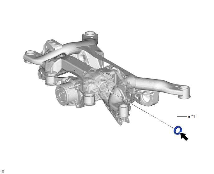
COMPONENTS
ILLUSTRATION
|
*1 | REAR DRIVE SHAFT OIL SEAL LH |
- | - |
|
● | Non-reusable part |
.png) |
MP grease |
Replacement
REPLACEMENT
CAUTION / NOTICE / HINT
The necessary procedures (adjustment, calibration, initialization, or registration) that must be performed after parts are removed and installed, or replaced during rear drive shaft oil seal LH removal/installation are shown below.
Necessary Procedures After Parts Removed/Installed/Replaced|
Replaced Part or Performed Procedure |
Necessary Procedure | Effect/Inoperative Function when Necessary Procedure not Performed |
Link |
|---|---|---|---|
| Rear wheel alignment adjustment |
|
|
|
|
Suspension, tires, etc. (The vehicle height changes because of suspension or tire replacement) |
Rear television camera assembly optical axis (Back camera position setting) |
Parking assist monitor system |
|
| Panoramic view monitor system |
|
HINT:
- Use the same procedure for the RH side and LH side.
- The following procedure is for the LH side.
PROCEDURE
1. REMOVE REAR DRIVE SHAFT ASSEMBLY LH
Click here .gif)
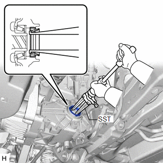
2. REMOVE REAR DRIVE SHAFT OIL SEAL LH
| (a) Using SST, tap out the rear drive shaft oil seal LH. SST: 09308-00010 NOTICE: Be careful not to damage the rear differential carrier sub-assembly. |
|
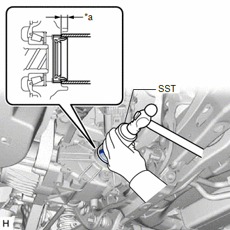
3. INSTALL REAR DRIVE SHAFT OIL SEAL LH
(a) Coat the lip of a new rear drive shaft oil seal LH with MP grease.
| (b) Using SST and a hammer, install the rear drive shaft oil seal LH to the rear differential carrier sub-assembly. SST: 09223-00010 Standard Depth: 6.7 to 7.7 mm (0.264 to 0.303 in.) NOTICE:
|
|
4. INSTALL REAR DRIVE SHAFT ASSEMBLY LH
Click here
READ NEXT:
 Steering Knuckle
ComponentsCOMPONENTS ILLUSTRATION
*1 FRONT LOWER BALL JOINT ASSEMBLY
*2 STEERING KNUCKLE
*3 FRONT AXLE HUB SUB-ASSEMBLY
*4 FRONT DISC BRAKE DUST COVER
*5
Drive Shaft System
PrecautionPRECAUTION
NOTICE OF REMOVING AND INSTALLING FRONT DRIVE SHAFT ASSEMBLY RH (for AWD)
(a) When removing and installing the front drive shaft assembly RH in an AWD vehicle, be sure to firs
SEE MORE:
Parts Location
PARTS LOCATION ILLUSTRATION
*1 INTAKE AIR CONTROL VALVE (for ACIS)
*2 ECM
*3 ENGINE ROOM RELAY BLOCK AND JUNCTION BLOCK ASSEMBLY
- EFI NO. 1 FUSE -
-
Open in Outer Mirror Indicator(Master) (C1AB4)
DESCRIPTION This DTC is stored when the blind spot monitor sensor RH detects an open in the outer rear view mirror indicator RH.
DTC No. Detection Item
DTC Detection Condition Trouble Area
C1AB4 Open in Outer Mirror Indicator(Master) Both of the following conditions are me
