
Toyota Camry (XV70): Rear Door Opening Trim Weatherstrip
Components
COMPONENTS
ILLUSTRATION
|
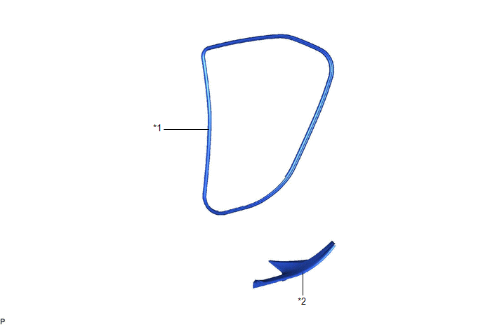
*1 | REAR DOOR OPENING TRIM WEATHERSTRIP |
*2 | REAR DOOR SCUFF PLATE |
Removal
REMOVAL
CAUTION / NOTICE / HINT
HINT:
- Use the same procedure for the RH side and LH side.
- The following procedure is for the LH side.
PROCEDURE
1. REMOVE REAR DOOR SCUFF PLATE
Click here .gif)
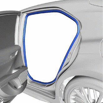
2. REMOVE REAR DOOR OPENING TRIM WEATHERSTRIP
| (a) Remove the rear door opening trim weatherstrip. |
|
Installation
INSTALLATION
CAUTION / NOTICE / HINT
HINT:
- Use the same procedure for the RH side and LH side.
- The following procedure is for the LH side.
PROCEDURE
1. INSTALL REAR DOOR OPENING TRIM WEATHERSTRIP
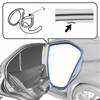
(a) Align the alignment mark on the rear door opening trim weatherstrip with the flange on the vehicle body indicated by the arrow in the illustration, and install the rear door opening trim weatherstrip.
|
*a | Alignment Mark |
.png) |
Flange Position |
NOTICE:
- Always align the alignment mark with the flange when installing the part. If the alignment mark is not aligned, water ingress may occur.
- After installation, check that the corners fit correctly.
HINT:
- Make sure to install the part of the rear door opening trim weatherstrip near the alignment mark first.
- The color of the alignment marks on the rear door opening trim weatherstrip LH and rear door opening trim weatherstrip RH are different.
Alignment Mark:
Location
Color
for LH Side
Red
for RH Side
Blue
2. INSTALL REAR DOOR SCUFF PLATE
Click here
.gif)
READ NEXT:
 Black Out Tape (for Front Door)
ComponentsCOMPONENTS ILLUSTRATION
*A for Front Passenger Side
*B for Driver Side
*1 COURTESY LIGHT ASSEMBLY
*2 FRONT ARMREST ASSEMBLY
*3 FRONT DO
Black Out Tape (for Rear Door)
ComponentsCOMPONENTS ILLUSTRATION
*1 REAR ARMREST ASSEMBLY
*2 REAR DOOR ARMREST COVER SUB-ASSEMBLY
*3 REAR DOOR INNER GLASS WEATHERSTRIP
*4 REAR DOOR NO. 2
SEE MORE:
Mute Signal Circuit between Radio Receiver and Telematics Transceiver
DESCRIPTION The DCM (telematics transceiver) sends a mute signal to the radio and display receiver assembly.
The radio and display receiver assembly controls the volume according to the mute signal from the DCM (telematics transceiver). WIRING DIAGRAM
CAUTION / NOTICE / HINT
NOTICE:
Depen
Evaporator Temperature Circuit or Evaporator Fin Thermistor (B1413)
DESCRIPTION The No. 1 cooler thermistor is installed to the evaporator in the air conditioner unit to detect the temperature of the cooled air that has passed through the evaporator, which is used to control the air conditioning system. It sends signals to the air conditioning amplifier assembly. Th
