Toyota Camry (XV70): Rear Window Defogger System does not Operate
DESCRIPTION
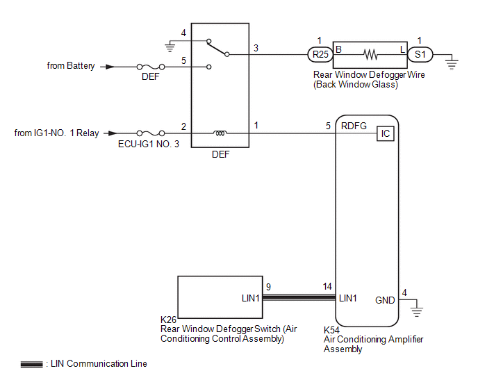
When the rear window defogger switch on the air conditioning control assembly is pressed, the operation signal is transmitted to the air conditioning amplifier assembly via LIN communication. When the air conditioning amplifier assembly receives the signal, it turns on the DEF relay to operate the window defogger system.
WIRING DIAGRAM
CAUTION / NOTICE / HINT
NOTICE:
- Inspect the fuses for circuits related to this system before performing the following procedure.
- If the battery voltage is low, the window defogger system may not operate due to operation of battery load control, check the Data List item "Battery Control Count (Body ECU)".
Click here
.gif)
PROCEDURE
|
1. | CHECK AIR CONDITIONING SYSTEM |
(a) Check the air conditioning system.
HINT:
Both the window defogger system operation signal and air conditioning system operation signal are transmitted to the air conditioning amplifier assembly via the same communication line.
OK:
The air conditioning system operates normally.
| NG | .gif) |
GO TO AIR CONDITIONING SYSTEM |
|
.gif)
|
2. | PERFORM ACTIVE TEST USING TECHSTREAM |
(a) Connect the Techstream to the DLC3.
(b) Turn the ignition switch to ON.
(c) Turn the Techstream on.
(d) Enter the following menus: Body Electrical / Air Conditioner / Active Test.
(e) Perform the Active Test according to the display on the Techstream.
Body Electrical > Air Conditioner > Active Test|
Tester Display | Measurement Item |
Control Range | Diagnostic Note |
|---|---|---|---|
|
Defogger Relay (Rear) |
Rear window defogger wire (Back window glass) |
OFF or ON | - |
|
Tester Display |
|---|
|
Defogger Relay (Rear) |
OK:
The window defogger system operates normally.
| NG | |
GO TO STEP 4 |
|
|
3. | REPLACE AIR CONDITIONING CONTROL ASSEMBLY |
(a) Replace the air conditioning control assembly with a new or known good one.
Click here
(b) Check that the window defogger system operates normally.
Click here
OK:
The window defogger system operates normally.
| OK | |
END (AIR CONDITIONING CONTROL ASSEMBLY WAS DEFECTIVE) |
| NG | |
REPLACE AIR CONDITIONING AMPLIFIER ASSEMBLY |
|
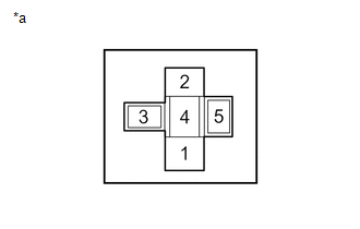
4. | INSPECT DEF RELAY |
(a) Inspect the DEF relay.
Click here
| NG | |
REPLACE DEF RELAY |
|
|
5. | CHECK HARNESS AND CONNECTOR (DEF RELAY - IG1-NO. 1 RELAY AND BATTERY) |
| (a) Remove the DEF relay from the engine room relay block and junction block assembly. |
|
(b) Measure the voltage according to the value(s) in the table below.
Standard Voltage:
|
Tester Connection | Condition |
Specified Condition |
|---|---|---|
|
DEF relay holder terminal-1 - Body ground |
Ignition switch ON |
11 to 14 V |
|
DEF relay holder terminal-5 - Body ground |
Always | 11 to 14 V |
| NG | |
REPAIR OR REPLACE HARNESS OR CONNECTOR |
|
|
6. | CHECK HARNESS AND CONNECTOR (DEF RELAY - AIR CONDITIONING AMPLIFIER ASSEMBLY) |
| (a) Remove the DEF relay from the engine room relay block and junction block assembly. |
|
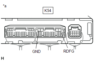
(b) Disconnect the K54 air conditioning amplifier assembly connector.
(c) Measure the resistance according to the value(s) in the table below.
Standard Resistance:
|
Tester Connection | Condition |
Specified Condition |
|---|---|---|
|
DEF relay holder terminal-1 - K54-5 (RDFG) |
Always | Below 1 Ω |
|
DEF relay holder terminal-1 or K54-5 (RDFG) - Body ground |
Always | 10 kΩ or higher |
| NG | |
REPAIR OR REPLACE HARNESS OR CONNECTOR |
|
|
7. | CHECK HARNESS AND CONNECTOR (DEF RELAY - REAR WINDOW DEFOGGER WIRE (BACK WINDOW GLASS)) |
| (a) Remove the DEF relay from the engine room relay block and junction block assembly. |
|
(b) Disconnect the R25 rear window defogger wire (back window glass) wire connector.
(c) Measure the resistance according to the value(s) in the table below.
Standard Resistance:
|
Tester Connection | Condition |
Specified Condition |
|---|---|---|
|
DEF relay holder terminal-3 - R25-1 (B) |
Always | Below 1 Ω |
|
DEF relay holder terminal-3 or R25-1 (B) - Body ground |
Always | 10 kΩ or higher |
| NG | |
REPAIR OR REPLACE HARNESS OR CONNECTOR |
|
|
8. | CHECK HARNESS AND CONNECTOR (REAR WINDOW DEFOGGER WIRE (BACK WINDOW GLASS) - BODY GROUND) |
(a) Disconnect the S1 rear window defogger wire (back window glass) connector.
(b) Measure the resistance according to the value(s) in the table below.
Standard Resistance:
|
Tester Connection | Condition |
Specified Condition |
|---|---|---|
|
S1-1 (L) - Body ground |
Always | Below 1 Ω |
| NG | |
REPAIR OR REPLACE HARNESS OR CONNECTOR |
|
|
9. | CHECK AIR CONDITIONING AMPLIFIER ASSEMBLY |
| (a) Reconnect the K54 air conditioning amplifier assembly connector. |
|
(b) Reinstall the DEF relay.
(c) Remove the air conditioning amplifier assembly with its connectors still connected.
Click here
(d) Measure the voltage according to the value(s) in the table below.
Standard Voltage:
|
Tester Connection | Condition |
Specified Condition |
|---|---|---|
|
K54-5 (RDFG) - K54-4 (GND) |
Ignition switch ON, rear window defogger switch on |
Below 1 V |
|
K54-5 (RDFG) - K54-4 (GND) |
Ignition switch ON, rear window defogger switch off |
11 to 14 V |
| OK | |
REPAIR OR REPLACE BACK WINDOW GLASS (REAR WINDOW DEFOGGER WIRE) |
| NG | |
REPLACE AIR CONDITIONING AMPLIFIER ASSEMBLY |
READ NEXT:
 Window Defogger Wire
On-vehicle InspectionON-VEHICLE INSPECTION PROCEDURE
1. CHECK REAR WINDOW DEFOGGER OPERATION (a) When the ignition switch is ON and the rear window defogger switch is pressed, check that the window
Components
COMPONENTS ILLUSTRATION
*1 COWL TOP VENTILATOR LOUVER SUB-ASSEMBLY
*2 FRONT FENDER TO COWL SIDE SEAL LH
*3 FRONT FENDER TO COWL SIDE SEAL RH
*4 FRONT WIPER
SEE MORE:
Pillar Speaker
ComponentsCOMPONENTS ILLUSTRATION
*1 FRONT DOOR OPENING TRIM WEATHERSTRIP
*2 FRONT NO. 3 SPEAKER ASSEMBLY
*3 FRONT PILLAR GARNISH
*4 CLIP
● Non-reusable part
- - RemovalREMOVAL CAUTION / NOTICE / HINT
HINT:
Use the same procedure
Microphone
ComponentsCOMPONENTS ILLUSTRATION
*A for Normal Roof
*B except Normal Roof
*1 ROOF CONSOLE BOX ASSEMBLY
*2 TELEPHONE MICROPHONE ASSEMBLY
*3 ROOF CONSOLE BOX SUB-ASSEMBLY
- - RemovalREMOVAL PROCEDURE
1. REMOVE ROOF CONSOLE BOX ASSEMBLY Clic
