Toyota Camry (XV70): Reassembly
REASSEMBLY
PROCEDURE
1. INSTALL FUEL PUMP
HINT:
Perform "Inspection After Repair" after replacing the fuel pump.
Click here .gif)
| (a) Apply gasoline to a new O-ring. Then install the O-ring and fuel pump spacer to the fuel pump. |
|
| (b) Install the fuel pump to the suction filter. |
|
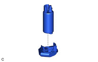
| (c) Engage the 3 claws to install the fuel pump to the fuel filter. NOTICE:
|
|
| (d) Connect the fuel pump harness connector to install the fuel pump harness to the fuel pump. |
|
| (e) Engage the claw to connect the fuel pump harness to the fuel pump. NOTICE:
|
|
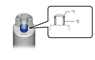
(f) Check the connection state of the fuel pump harness.
(1) Measure the resistance according to the value(s) in the table below.
Standard Resistance:
|
Tester Connection | Condition |
Specified Condition |
|---|---|---|
|
Fuel pump body - Ground terminal of the fuel pump harness |
Always | Below 1 Ω |
If the result is not as specified, reconnect the fuel pump harness to the fuel pump so that the ground terminal of the fuel pump harness is securely connected to the fuel pump body.
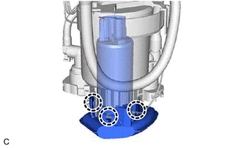
(g) Engage the 2 claws to install the fuel filter to the fuel sub-tank.
NOTICE:
- Do not apply excessive force to the tube or No. 1 fuel suction support.
- Securely engage the claws.
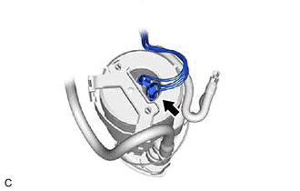
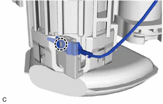
| (h) Engage the clamp and claw, and connect the fuel pump filter hose while aligning it with the installation position of the fuel sub-tank. NOTICE: Securely engage the clamp and claw. |
|

(i) Engage the clamp to connect the fuel pump harness to the fuel suction plate sub-assembly.
(j) Connect the 2 fuel pump harness connectors.
(k) Install the harness protector to the fuel pump harness.
2. INSTALL FUEL SENDER GAUGE ASSEMBLY
Click here
READ NEXT:
 Installation
INSTALLATION PROCEDURE 1. INSTALL FUEL SUCTION TUBE WITH PUMP AND GAUGE ASSEMBLY
(a) Install a new fuel suction tube set gasket to the fuel tank assembly.
(b) Set the fuel suction tube with pump a
Components
COMPONENTS ILLUSTRATION
*1 REAR CENTER SEAT OUTER BELT ASSEMBLY
*2 REAR SEAT CUSHION ASSEMBLY
*3 REAR SEAT CUSHION LOCK HOOK
*4 REAR SEAT INNER BELT ASSEMBLY RH
Removal
REMOVAL CAUTION / NOTICE / HINT
The necessary procedures (adjustment, calibration, initialization or registration) that must be performed after parts are removed and installed, or replaced during fu
SEE MORE:
Road Test
ROAD TEST
HINT:
The dynamic radar cruise control system has 2 cruise control modes: constant speed control mode and vehicle-to-vehicle distance control mode.
Vehicle-to-vehicle distance control mode is selected by default when the dynamic radar cruise control system is turned on using the
Installation
INSTALLATION PROCEDURE 1. INSTALL FRONT ENGINE MOUNTING INSULATOR
(a) Install the stay to the front engine mounting insulator with the nut.
Torque: 6.0 N·m {61 kgf·cm, 53 in·lbf} (b) Install the front engine mounting insulator to the front frame assembly with the 3 nuts.
Torque: 72 N·m {
