Toyota Camry (XV70): Removal
REMOVAL
PROCEDURE
1. PRECAUTION (w/o Navigation System)
NOTICE:
- When replacing the radio and display receiver assembly, always replace it with a new one. If a radio and display receiver assembly which was installed to another vehicle is used, the following may occurs:
- A communication malfunction DTC may be stored.
- The radio and display receiver assembly may not operate normally.
NOTICE:
Click here .gif)
2. PRECAUTION (w/ Navigation System)
NOTICE:
- When replacing the radio and display receiver assembly or navigation ECU, always replace it with a new one. If a radio and display receiver assembly or navigation ECU which was installed to another vehicle is used, the following may occur:
- A communication malfunction DTC may be stored.
- The radio and display receiver assembly or navigation ECU may not operate normally.
- After replacing the radio and display receiver assembly, if "New software is not compatible with the system. Contact your dealer." is displayed on the multi-display, update the software of the navigation ECU.
NOTICE:
Click here
3. REMOVE AIR CONDITIONING CONTROL ASSEMBLY
Click here
4. REMOVE LOWER INSTRUMENT PANEL FINISH PANEL ASSEMBLY
Click here
5. REMOVE CENTER INSTRUMENT CLUSTER FINISH PANEL SUB-ASSEMBLY (for 7 Inch Display)
Click here
6. REMOVE CENTER INSTRUMENT CLUSTER FINISH PANEL SUB-ASSEMBLY (for 9 Inch Display)
Click here
7. REMOVE CENTER INSTRUMENT CLUSTER FINISH PANEL ASSEMBLY
Click here
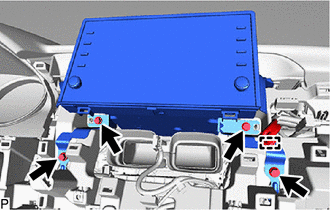
8. REMOVE RADIO AND DISPLAY RECEIVER ASSEMBLY WITH BRACKET (for 7 Inch Display)
| (a) Disengage the clamp. |
|
(b) Remove the 4 bolts.
(c) Disengage the 2 clips and 2 claws as shown in the illustration.
.png) |
Place Hand Here |
.png) |
Remove in this Direction |
(d) Disengage the 2 guides as shown in the illustration.
|
|
Remove in this Direction |
(e) Disconnect each connector and remove the radio and display receiver assembly with bracket.
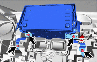
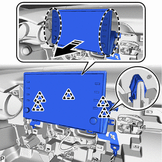
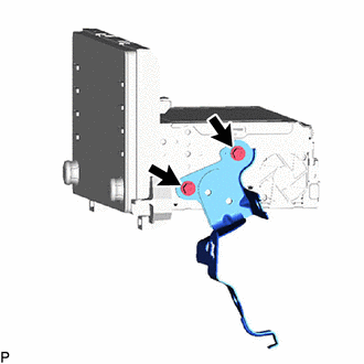
9. REMOVE RADIO AND DISPLAY RECEIVER ASSEMBLY WITH BRACKET (for 9 Inch Display)
| (a) Disengage the clamp. |
|
(b) Remove the 4 bolts.
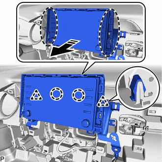
(c) Disengage the 5 clips as shown in the illustration.
|
|
Place Hand Here |
|
|
Remove in this Direction |
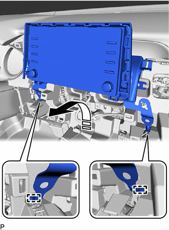
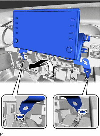
(d) Disengage the 2 guides as shown in the illustration.
|
|
Remove in this Direction |
(e) Disconnect each connector and remove the radio and display receiver assembly with bracket.
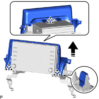
10. REMOVE CENTER INSTRUMENT CLUSTER FINISH UPPER PANEL ASSEMBLY (for 7 Inch Display)
(a) Disengage the 3 clips to remove the center instrument cluster finish upper panel assembly as shown in the illustration.
|
|
Remove in this Direction |
11. REMOVE NO. 2 RADIO RECEIVER BRACKET
| (a) Remove the 2 screws and No. 2 radio receiver bracket. |
|
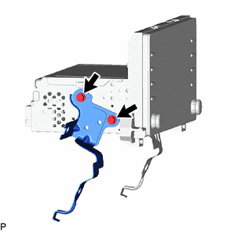
12. REMOVE NO. 1 RADIO RECEIVER BRACKET
| (a) Remove the 2 screws and No. 1 radio receiver bracket. |
|
13. REMOVE RADIO AND DISPLAY RECEIVER ASSEMBLY
READ NEXT:
 Installation
INSTALLATION PROCEDURE 1. PRECAUTION (w/o Navigation System)
NOTICE:
When replacing the radio and display receiver assembly, always replace it with a new one. If a radio and display receiver ass
Components
COMPONENTS ILLUSTRATION
*1 REAR ARMREST ASSEMBLY
*2 REAR DOOR ARMREST COVER SUB-ASSEMBLY
*3 REAR DOOR INNER GLASS WEATHERSTRIP
*4 REAR DOOR NO. 2 SERVICE HOLE COV
SEE MORE:
Removal
REMOVAL CAUTION / NOTICE / HINT
CAUTION: If the luggage compartment door support assembly is removed, the luggage compartment door will slam shut. Make sure to support the luggage compartment door by hand when it is open and when opening and closing it. PROCEDURE
1. REMOVE SPARE WHEEL COVER AS
Satellite Radio Broadcast cannot be Selected or After Selecting Broadcast, Broadcast cannot be Added into Memory
CAUTION / NOTICE / HINT NOTICE: Some satellite radio broadcasts require payment. A contract must be made between a satellite radio company and the user. If the contract expires, it will not be possible to listen to the broadcast. PROCEDURE
1.
CHECK SATELLITE RADIO (a) Check radio condi
