Toyota Camry (XV70): Removal
REMOVAL
CAUTION / NOTICE / HINT
The necessary procedures (adjustment, calibration, initialization or registration) that must be performed after parts are removed and installed, or replaced generator assembly removal/installation are shown below.
Necessary Procedures After Parts Removed/Installed/Replaced|
Replaced Part or Performed Procedure |
Necessary Procedure | Effect/Inoperative Function when Necessary Procedure not Performed |
Link |
|---|---|---|---|
|
Battery terminal is disconnected/reconnected |
Perform steering sensor zero point calibration |
Lane Tracing Assist System |
|
|
Pre-collision System | |||
|
Memorize steering angle neutral point |
Parking assist monitor system |
| |
|
Panoramic view monitor system |
| ||
|
Front bumper assembly (w/ Panoramic view monitor system) |
Front television camera view adjustment |
Panoramic view monitor system |
|
PROCEDURE
1. PRECAUTION
NOTICE:
After turning the engine switch off, waiting time may be required before disconnecting the cable from the negative (-) battery terminal. Therefore, make sure to read the disconnecting the cable from the negative (-) battery terminal notices before proceeding with work.
Click here .gif)
2. DISCONNECT CABLE FROM NEGATIVE BATTERY TERMINAL
NOTICE:
When disconnecting the cable, some systems need to be initialized after the cable is reconnected.
Click here
3. REMOVE RADIATOR ASSEMBLY
Click here
4. REMOVE V-BANK COVER SUB-ASSEMBLY
Click here
5. REMOVE V-RIBBED BELT
Click here
6. REMOVE GENERATOR ASSEMBLY
| (a) Open the terminal cap. |
|
(b) Remove the nut and disconnect the wire harness from terminal B.
(c) Remove the 2 bolts.
| (d) Disconnect the generator assembly connector. |
|
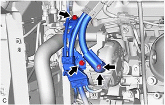
(e) Disconnect the compressor assembly with magnetic clutch connector.
(f) Disconnect the camshaft timing oil control solenoid assembly connector.
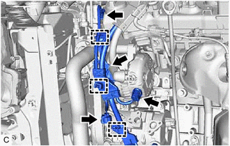
(g) Disengage the 3 wire harness clamps and remove the wire harness clamp bracket.
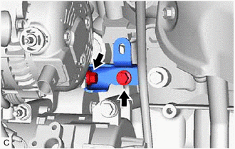
| (h) Remove the 2 bolts and generator assembly bracket. |
|
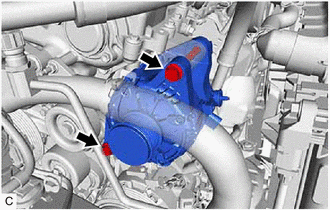
| (i) Remove the 2 bolts and generator assembly. |
|
READ NEXT:
 Disassembly
DISASSEMBLY PROCEDURE 1. REMOVE GENERATOR PULLEY CAP
(a) Using a screwdriver, remove the generator pulley cap from the generator pulley with clutch.
NOTICE:
Do not reuse the generator p
Inspection
INSPECTION PROCEDURE 1. INSPECT GENERATOR BRUSH HOLDER ASSEMBLY
(a) Using a vernier caliper, measure the length of the exposed brushes.
Standard Exposed Brush Length: 9.5 to 11.5 mm (0.374 t
Reassembly
REASSEMBLY PROCEDURE 1. INSTALL GENERATOR DRIVE END FRAME BEARING
(a) Using SST and a press, install a new generator drive end frame bearing to the generator drive end frame.
SST: 09950-60010
SEE MORE:
Inspection
INSPECTION PROCEDURE 1. INSPECT REAR SPEAKER ASSEMBLY (for 6 Speakers)
(a) With the speaker installed, check that there is no looseness or other abnormalities.
(b) Check that there is no foreign matter in the speaker, no tears on the speaker cone or other abnormalities.
(c) Measure the res
Rear Side Marker Light Bulb
ComponentsCOMPONENTS ILLUSTRATION
*1 REAR COMBINATION LIGHT ASSEMBLY
*2 REAR COMBINATION LIGHT COVER
*3 REAR SIDE MARKER LIGHT BULB
- - RemovalREMOVAL CAUTION / NOTICE / HINT
HINT:
Use the same procedure for the RH side and LH side.
The following pr
