Toyota Camry (XV70): Removal
REMOVAL
CAUTION / NOTICE / HINT
The necessary procedures (adjustment, calibration, initialization, or registration) that must be performed after parts are removed and installed, or replaced during rear stabilizer bar removal/installation are shown below.
Necessary Procedures After Parts Removed/Installed/Replaced|
Replaced Part or Performed Procedure |
Necessary Procedure | Effect/Inoperative Function when Necessary Procedure not Performed |
Link |
|---|---|---|---|
| Inspection After Repair |
|
|
CAUTION:
To prevent burns, do not touch the engine, exhaust pipe or other high temperature components while the engine is hot.
PROCEDURE
1. REMOVE REAR WHEEL
Click here .gif)
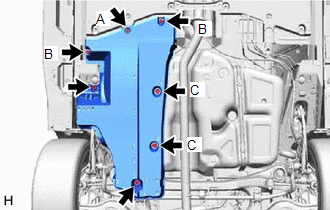
2. REMOVE NO. 2 FLOOR UNDER COVER
| (a) Remove the 2 bolts and clip (A). |
|
(b) Disengage the 2 grommets (B) and 2 clips (C) to remove the No. 2 floor under cover.
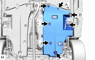
3. REMOVE NO. 1 FLOOR UNDER COVER
| (a) Remove the 2 bolts and clip (A). |
|
(b) Disengage the 2 grommets (B) and 2 clips (C) to remove the No. 1 floor under cover.
4. REMOVE CENTER EXHAUST PIPE ASSEMBLY
for A25A-FKS: Click here
for 2GR-FKS: Click here
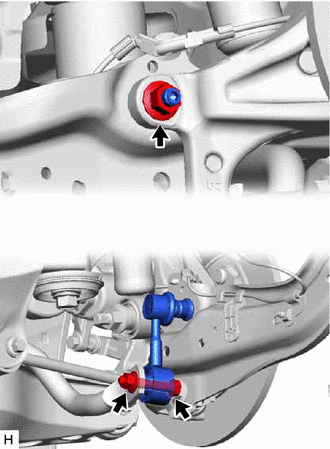
5. REMOVE REAR STABILIZER LINK ASSEMBLY LH
| (a) Loosen the nut (A) of the rear stabilizer link assembly LH. HINT: If the ball joint turns together with the nut, use a 6 mm hexagon socket wrench to hold the stud bolt. |
|

(b) Loosen the nut (B) of the rear stabilizer link assembly LH.
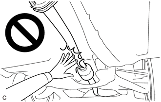
| (c) Using a jack and a wooden block, support the rear No. 2 suspension arm assembly. NOTICE:
|
|
.png)
| (d) Remove the bolt, 2 nuts and rear stabilizer link assembly LH. |
|
6. REMOVE REAR STABILIZER LINK ASSEMBLY RH
HINT:
Perform the same procedure as for the LH side.
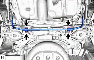
7. REMOVE REAR STABILIZER BAR
| (a) Remove the 4 bolts, rear stabilizer bar, 2 rear No. 1 stabilizer bar brackets and 2 rear stabilizer bushings from the rear suspension member sub-assembly. |
|
8. REMOVE REAR NO. 1 STABILIZER BAR BRACKET
| (a) Remove the 2 rear No. 1 stabilizer bar brackets from the 2 rear stabilizer bushings. |
|

9. REMOVE REAR STABILIZER BUSHING
| (a) Remove the 2 rear stabilizer bushings from the rear stabilizer bar. |
|

READ NEXT:
 Inspection
INSPECTION PROCEDURE 1. INSPECT REAR STABILIZER LINK ASSEMBLY
(a) Inspect the turning torque of the ball joint.
(1) Secure the rear stabilizer link assembly in a vise using aluminum plates.
NOT
Installation
INSTALLATION PROCEDURE 1. INSTALL REAR STABILIZER BUSHING
(a) Install the 2 rear stabilizer bushings to the rear stabilizer bar.
NOTICE: Be sure to install the rear stabilizer bushings so that eac
SEE MORE:
Installation
INSTALLATION PROCEDURE 1. INSTALL TRANSMISSION OIL COOLER
(a) Temporarily install the transmission oil cooler to the automatic transaxle case sub-assembly with the bolt (A).
(b) Install the bolt (B). Torque: 13.5 N
Reassembly
REASSEMBLY PROCEDURE 1. CLEAN VACUUM PUMP HOUSING
(a) Clean the inside surface of the vacuum pump housing. 2. INSTALL VACUUM PUMP ROTOR
(a) Clean the vacuum pump rotor. (b) Apply engine oil to the areas of the vacuum pump rotor shown in the illustration.
Engine Oil (c) Instal
