Toyota Camry (XV70): Removal
REMOVAL
CAUTION / NOTICE / HINT
The necessary procedures (adjustment, calibration, initialization, or registration) that must be performed after parts are removed and installed, or replaced during rear trailing arm assembly removal/installation are shown below.
Necessary Procedures After Parts Removed/Installed/Replaced|
Replaced Part or Performed Procedure |
Necessary Procedure | Effect/Inoperative Function when Necessary Procedure not Performed |
Link |
|---|---|---|---|
| Rear wheel alignment adjustment |
|
|
|
|
Suspension, tires, etc. (The vehicle height changes because of suspension or tire replacement) |
Rear television camera assembly optical axis (Back camera position setting) |
Parking assist monitor system |
|
| Panoramic view monitor system |
|
HINT:
- Use the same procedure for the RH side and LH side.
- The following procedure is for the LH side.
PROCEDURE
1. REMOVE REAR WHEEL
Click here
.gif)
2. REMOVE NO. 2 FLOOR UNDER COVER (for 2WD)
(a) for LH Side:
Click here
3. REMOVE NO. 1 FLOOR UNDER COVER (for 2WD)
(a) for RH Side:
Click here
4. REMOVE NO. 2 FLOOR UNDER COVER (for AWD)
(a) for LH Side:
| (1) Remove the bolt and 2 clips (A). |
|
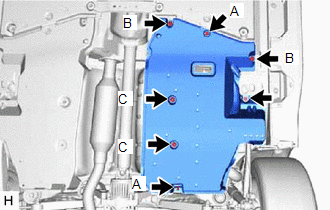
(2) Disengage the 2 grommets (B) and 2 clips (C) to remove the No. 2 floor under cover.
5. REMOVE NO. 1 FLOOR UNDER COVER (for AWD)
(a) for RH Side:
| (1) Remove the bolt and 2 clips (A). |
|
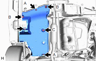
(2) Disengage the 2 grommets (B) and clip (C) to remove the No. 1 floor under cover.
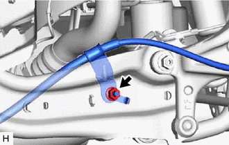
6. SEPARATE NO. 3 PARKING BRAKE CABLE ASSEMBLY (w/o Electric Parking Brake System)
| (a) Remove the nut and separate the No. 3 parking brake cable assembly from the rear trailing arm assembly. |
|
7. SEPARATE SKID CONTROL SENSOR WIRE (w/o Electric Parking Brake System)
| (a) Disengage the 2 clamps. |
|
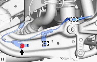
(b) Remove the bolt and separate the skid control sensor wire from the rear trailing arm assembly.
8. SEPARATE NO. 2 PARKING BRAKE WIRE ASSEMBLY (w/ Electric Parking Brake System)
| (a) Disengage the 2 clamps. |
|
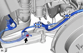
(b) Remove the nut and separate the No. 2 parking brake wire assembly from the rear trailing arm assembly.
9. REMOVE REAR STABILIZER LINK ASSEMBLY (for 2WD)
Click here
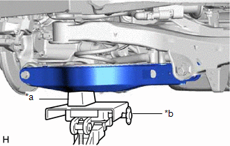
10. REMOVE REAR TRAILING ARM ASSEMBLY
| (a) Using a transmission jack and a wooden block, support the rear No. 2 suspension arm assembly. NOTICE:
|
|
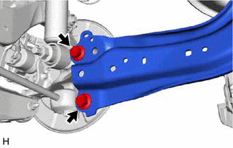
(b) for 2WD:
| (1) Remove the 2 bolts and separate the rear trailing arm assembly from the rear axle carrier sub-assembly. |
|
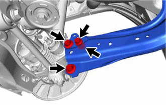
(c) for AWD:
| (1) Remove the 3 bolts, nut and separate the rear trailing arm assembly from the rear axle carrier sub-assembly. |
|
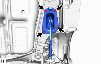
| (d) Remove the 4 bolts and rear trailing arm assembly. |
|
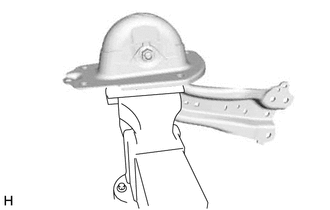
11. REMOVE REAR SUSPENSION ARM COVER
| (a) Secure the rear trailing arm assembly in a vise using aluminum plates. NOTICE: Do not overtighten the vise. |
|
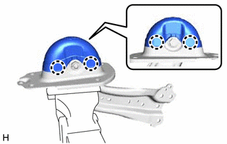
| (b) Disengage the 4 claws and remove the rear suspension arm cover. |
|
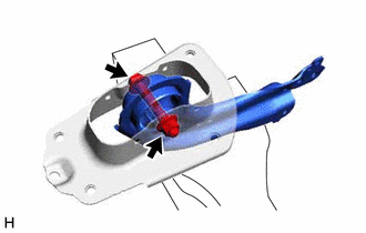
12. REMOVE REAR SUSPENSION ARM BRACKET
| (a) Remove the bolt, nut and rear suspension arm bracket from the rear trailing arm assembly. NOTICE: Because the bolt has its own stopper, do not turn the bolt. Loosen the nut with the bolt secured. |
|
READ NEXT:
 Installation
INSTALLATION CAUTION / NOTICE / HINT
HINT:
Use the same procedure for the RH side and LH side.
The following procedure is for the LH side.
PROCEDURE 1. INSTALL REAR SUSPENSION ARM BRACKE
Components
COMPONENTS ILLUSTRATION
*A for 2WD
- -
*1 REAR SUSPENSION MEMBER SUB-ASSEMBLY
*2 REAR UPPER CONTROL ARM ASSEMBLY LH
*3 REAR UPPER CONTROL ARM ASSEMBLY R
SEE MORE:
Intake Air Temperature Sensor 1 Bank 1 Circuit Short to Battery or Open (P011015)
DESCRIPTION Refer to DTC P011011. Click here
HINT: When DTC P011015 is stored, the ECM enters fail-safe mode. During fail-safe mode, the intake air temperature is estimated to be 20°C (68°F) by the ECM. Fail-safe mode continues until a pass condition is detected, and the engine switch is then
Left Rear Wheel Speed Sensor Signal Stuck High (C050C24)
DESCRIPTION Refer to DTC C050C12 Click here
DTC No. Detection Item
DTC Detection Condition Trouble Area
C050C24 Left Rear Wheel Speed Sensor Signal Stuck High
The speed sensor signal is not within the specified range for 5 seconds or more.
Rear speed sensor L
