
Toyota Camry (XV70): Installation
Toyota Camry Repair Manual XV70 (2018-2024) / Suspension / Rear Suspension / Rear Trailing Arm / Installation
INSTALLATION
CAUTION / NOTICE / HINT
HINT:
- Use the same procedure for the RH side and LH side.
- The following procedure is for the LH side.
PROCEDURE
1. INSTALL REAR SUSPENSION ARM BRACKET
| (a) Temporarily install the rear suspension arm bracket to the rear trailing arm assembly with the bolt and nut. NOTICE: Insert the bolt from the inside of the vehicle. |
|
.png)
| (b) Position the rear trailing arm assembly as shown in the illustration. Reference Length (A):
|
|
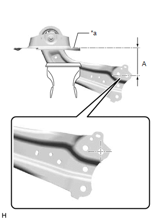
(c) Fully tighten the nut.
Torque:
120 N
READ NEXT:
 Components
COMPONENTS ILLUSTRATION
*A for 2WD
- -
*1 REAR SUSPENSION MEMBER SUB-ASSEMBLY
*2 REAR UPPER CONTROL ARM ASSEMBLY LH
*3 REAR UPPER CONTROL ARM ASSEMBLY R
Removal
REMOVAL CAUTION / NOTICE / HINT
The necessary procedures (adjustment, calibration, initialization, or registration) that must be performed after parts are removed and installed, or replaced during r
SEE MORE:
Inspection
INSPECTION PROCEDURE 1. INSPECT STEERING WHEEL SWITCH HOUSING
*a Component without harness connected
(Steering Wheel Switch Housing)
- -
(a) Measure the resistance according to the value(s) in the table below.
Standard Resistance: Light Switch Circuit
Tes
Parts Location
PARTS LOCATION ILLUSTRATION
*1 DEF RELAY
*2 REAR WINDOW DEFOGGER WIRE
*3 ENGINE ROOM RELAY BLOCK AND JUNCTION BLOCK ASSEMBLY
- DEF FUSE *4
BACK WINDOW GLASS ILLUSTRATION
*1 REAR WINDOW DEFOGGER SWITCH (AIR CONDITIONING CONTROL ASSEM
© 2023-2026 Copyright www.tocamry.com
