Toyota Camry (XV70): Removal
REMOVAL
CAUTION / NOTICE / HINT
HINT:
- Use the same procedure for the RH side and LH side.
- The following procedure is for the LH side.
PROCEDURE
1. REMOVE SPARE WHEEL COVER ASSEMBLY
Click here .gif)
2. REMOVE SPARE WHEEL COVER TRAY
Click here
3. REMOVE NO. 1 LUGGAGE COMPARTMENT TRIM HOOK
Click here
4. REMOVE LUGGAGE COMPARTMENT DOOR STRIKER COVER
Click here
5. REMOVE REAR FLOOR FINISH PLATE
Click here
6. REMOVE LUGGAGE COMPARTMENT TRIM INNER COVER RH (for RH Side)
Click here
7. REMOVE LUGGAGE COMPARTMENT TRIM INNER COVER LH (for LH Side)
Click here
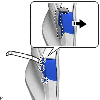
8. REMOVE REAR COMBINATION LIGHT COVER
(a) Using a moulding remover, disengage the 3 claws as shown in the illustration.
.png) |
Insert Moulding Remover Here |
.png) |
Remove in this Direction |
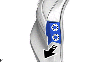
(b) Disengage the 2 claws to remove the rear combination light cover as shown in the illustration.
|
|
Remove in this Direction |
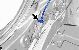
9. REMOVE REAR COMBINATION LIGHT ASSEMBLY
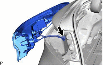
| (a) Disconnect the connector. |
|
(b) Apply protective tape around the rear combination light assembly as shown in the illustration.
.png) |
Protective Tape |
| (c) Remove the 2 screws. |
|
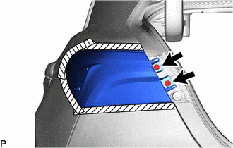
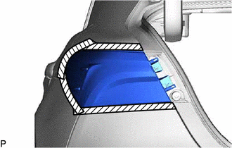
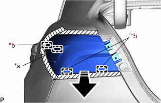
(d) Pull the rear combination light assembly toward the rear of the vehicle as shown in the illustration to disengage the pin and 3 guides and separate the rear combination light assembly.
NOTICE:
To prevent the rear combination light assembly from falling when disengaging the pin and guides, lightly hold the rear combination light assembly.
|
*a | Pin |
|
*b | Guide |
|
|
Remove in this Direction |
| (e) Disengage the grommet to remove the rear combination light assembly. |
|
READ NEXT:
 Disassembly
DISASSEMBLY CAUTION / NOTICE / HINT
HINT:
Use the same procedure for the RH side and LH side.
The following procedure is for the LH side.
PROCEDURE 1. REMOVE REAR SIDE MARKER LIGHT
Inspection
INSPECTION PROCEDURE 1. INSPECT REAR COMBINATION LIGHT LED (for Bulb Type Back-up Light)
*a Component without harness connected
(Rear Combination Light LED) (a) Apply battery vo
Reassembly
REASSEMBLY CAUTION / NOTICE / HINT
HINT:
Use the same procedure for the RH side and LH side.
The following procedure is for the LH side.
PROCEDURE 1. INSTALL REAR COMBINATION LIGHT
SEE MORE:
Vehicle Speed Signal Circuit between Radio Receiver and Combination Meter
DESCRIPTION for Automatic Sound Levelizer (ASL):
This circuit is necessary for the Automatic Sound Levelizer (ASL) built into the radio and display receiver assembly.
The Automatic Sound Levelizer (ASL) function automatically adjusts the audio system volume in order to compensate for increase
Components
COMPONENTS ILLUSTRATION
*1 FRONT FLOOR COVER LH
*2 FRONT FLOOR COVER RH
N*m (kgf*cm, ft.*lbf): Specified torque
- - ILLUSTRATION
*1 NO. 1 ENGINE UNDER COVER
*2 FRONT WHEEL OPENING EXTENSION PAD LH
*3 FRONT WHEEL OPENING EXTE
