Toyota Camry (XV70): Removal
REMOVAL
CAUTION / NOTICE / HINT
The necessary procedures (adjustment, calibration, initialization, or registration) that must be performed after parts are removed, installed, or replaced during the steering wheel switch housing removal/installation are shown below.
Necessary Procedures After Parts Removed/Installed/Replaced|
Replaced Part or Performed Procedure |
Necessary Procedure | Effect/Inoperative Function when Necessary Procedure not Performed |
Link |
|---|---|---|---|
|
Removal/installation of the spiral cable with sensor sub-assembly |
| Parking assist monitor system |
|
|
Steering angle neutral point (Initialize panoramic view monitor system) |
Panoramic view monitor system |
| |
|
Disconnect cable from negative battery terminal |
Perform steering sensor zero point calibration |
Lane tracing assist system |
|
|
Pre-collision system | |||
|
Memorize steering angle neutral point |
Parking assist monitor system |
| |
|
Panoramic view monitor system |
|
CAUTION:
Some of these service operations affect the SRS airbag system. Read the precautionary notices concerning the SRS airbag system before servicing.
.png)
Click here
.gif)
PROCEDURE
1. REMOVE SPIRAL CABLE WITH SENSOR SUB-ASSEMBLY
Click here
2. REMOVE WINDSHIELD WIPER SWITCH ASSEMBLY
Click here
3. REMOVE TURN SIGNAL SWITCH
Click here
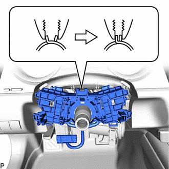
4. REMOVE STEERING WHEEL SWITCH HOUSING
| (a) Using pliers, expand the clamp as shown in the illustration. |
|
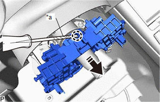
(b) While holding the clamp expanded, using a screwdriver with its tip wrapped with protective tape, disengage the claw and remove the steering wheel switch housing as shown in the illustration.
|
*a | Protective Tape |
.png) |
Remove in this Direction |
READ NEXT:
 Inspection
INSPECTION PROCEDURE 1. INSPECT STEERING WHEEL SWITCH HOUSING
*a Component without harness connected
(Steering Wheel Switch Housing)
- -
(a) Measure the resistance ac
Installation
INSTALLATION PROCEDURE 1. INSTALL STEERING WHEEL SWITCH HOUSING
(a) When reusing the steering wheel switch housing:
(1) Using pliers, expand the clamp and temporarily install the steering wh
SEE MORE:
Precaution
PRECAUTION INITIALIZATION NOTICE: Make sure to perform the necessary procedures (adjustment, calibration, initialization, or registration) after parts related to the cooling fan system have been removed/installed or replaced.
Click here
Portable Player cannot be Connected Manually/Automatically
CAUTION / NOTICE / HINT HINT: Some versions of "Bluetooth" compatible audio players may not function properly, or the functions may be limited using the radio and display receiver assembly, even if the portable audio player itself can play files.
Click here
PROCEDURE
1.
CHECK C
