
Toyota Camry (XV70): Removal
REMOVAL
CAUTION / NOTICE / HINT
The necessary procedures (adjustment, calibration, initialization or registration) that must be performed after parts are removed and installed, or replaced during door control and tire pressure warning ECU and receiver or electrical key and tire pressure warning ECU and receiver removal/installation are shown below.
|
Replacement Part or Procedure |
Necessary Procedures | Effects/Inoperative when not Performed |
Link |
|---|---|---|---|
|
*1: When performing learning using the Techstream.
Click here | |||
|
Disconnect cable from negative battery terminal |
Perform steering sensor zero point calibration |
Lane Tracing Assist System |
|
|
Pre-collision system | |||
|
Parking Support Brake System*1 | |||
|
Memorize steering angle neutral point |
Parking assist monitor system |
| |
|
Panoramic view monitor system |
| ||
|
|
|
|
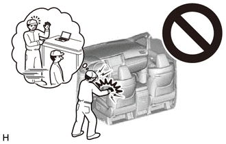
CAUTION:
Some of these service operations affect the SRS airbag system. Read the precautionary notices concerning the SRS airbag system before servicing.
Click here

NOTICE:
When replacing the door control and tire pressure warning ECU and receiver or electrical key and tire pressure warning ECU and receiver, read the transmitter IDs stored in the old ECU using the Techstream and write them down before removal.
Click here
PROCEDURE
1. PRECAUTION
NOTICE:
After turning the ignition switch off, waiting time may be required before disconnecting the cable from the negative (-) battery terminal. Therefore, make sure to read the disconnecting the cable from the negative (-) battery terminal notices before proceeding with work.
Click here
2. DISCONNECT CABLE FROM NEGATIVE BATTERY TERMINAL
for A25A-FKS:
Click here
for 2GR-FKS:
Click here
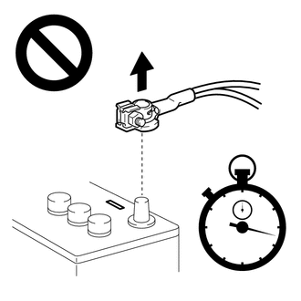
CAUTION:
- Wait at least 90 seconds after disconnecting the cable from the negative (-) battery terminal to disable the SRS system.
- If an airbag deploys for any reason, it may cause a serious injury.
3. REMOVE REAR SEAT ASSEMBLY (for Fixed Seat Type)
Click here
4. REMOVE REAR SEAT CUSHION ASSEMBLY (for Fold Down Seat Type)
Click here
5. REMOVE REAR SEAT CUSHION LOCK HOOK (for Fold Down Seat Type)
Click here
6. DISCONNECT REAR DOOR OPENING TRIM WEATHERSTRIP RH
HINT:
Use the same procedure as for the LH side.
Click here
7. REMOVE REAR SIDE SEATBACK ASSEMBLY RH (for Fold Down Seat Type)
HINT:
Use the same procedure as for the LH side.
Click here
8. REMOVE INNER ROOF SIDE GARNISH RH
HINT:
Use the same procedure as for the LH side.
Click here
9. REMOVE DOOR CONTROL AND TIRE PRESSURE WARNING ECU AND RECEIVER (w/o Smart Key System)
NOTICE:
- Do not drop, strike or otherwise subject the door control and tire pressure warning ECU and receiver to impact.
- If the door control and tire pressure warning ECU and receiver is subjected to an impact, replace it with a new one.
| (a) Remove the bolt. |
|
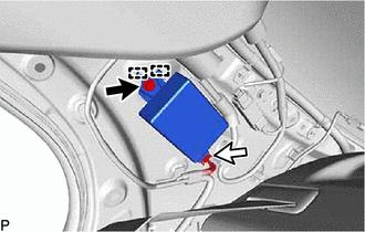
(b) Disengage the 2 guides.
(c) Disconnect the connector to remove the door control and tire pressure warning ECU and receiver.
10. REMOVE ELECTRICAL KEY AND TIRE PRESSURE WARNING ECU AND RECEIVER (w/ Smart Key System)
NOTICE:
- Do not drop, strike or otherwise subject the electrical key and tire pressure warning ECU and receiver to impact.
- If the electrical key and tire pressure warning ECU and receiver is subjected to an impact, replace it with a new one.
| (a) Remove the bolt. |
|
(b) Disengage the 2 guides.
(c) Disconnect the connector to remove the electrical key and tire pressure warning ECU and receiver.
READ NEXT:
 Installation
INSTALLATION PROCEDURE 1. INSTALL DOOR CONTROL AND TIRE PRESSURE WARNING ECU AND RECEIVER (w/o Smart Key System)
NOTICE:
Do not drop, strike or otherwise subject the door control and tire pressure
Door Control Switch
ComponentsCOMPONENTS ILLUSTRATION
*1 DOOR CONTROL SWITCH ASSEMBLY
*2 POWER WINDOW REGULATOR SWITCH ASSEMBLY WITH FRONT DOOR UPPER ARMREST BASE PANEL RemovalREMOVAL PROCEDURE
1. REM
Door Control Transmitter (w/ Smart Key System)
ComponentsCOMPONENTS ILLUSTRATION
*1 TRANSMITTER BATTERY
*2 MECHANICAL KEY
*3 TRANSMITTER HOUSING COVER
*4 TRANSMITTER HOUSING CASE
*5 SMART KEY DOOR CONTROL T
SEE MORE:
Road Test
ROAD TEST
HINT:
The dynamic radar cruise control system has 2 cruise control modes: constant speed control mode and vehicle-to-vehicle distance control mode.
Vehicle-to-vehicle distance control mode is selected by default when the dynamic radar cruise control system is turned on using the
Components
COMPONENTS ILLUSTRATION
*1 VVT SENSOR (for Intake Side of Bank 1)
*2 VVT SENSOR (for Exhaust Side of Bank 1)
*3 VVT SENSOR (for Intake Side of Bank 2)
*4 VVT SENSOR (for Exhaust Side of Bank 2)
N*m (kgf*cm, ft.*lbf): Specified torque
