
Toyota Camry (XV70): Removal
REMOVAL
CAUTION / NOTICE / HINT
The necessary procedures (adjustment, calibration, initialization, or registration) that must be performed after parts are removed and installed, or replaced during compressor assembly with magnetic clutch removal/installation are shown below.
Necessary Procedure After Parts Removed/Installed/Replaced|
Replaced Part or Performed Procedure |
Necessary Procedure | Effect/Inoperative Function when Necessary Procedure not Performed |
Link |
|---|---|---|---|
| Front bumper assembly (w/ Panoramic view monitor system) |
Front television camera view adjustment |
Panoramic view monitor system |
|
PROCEDURE
1. RECOVER REFRIGERANT FROM REFRIGERATION SYSTEM
Click here
.gif)
2. REMOVE V-RIBBED BELT
Click here
3. REMOVE RADIATOR ASSEMBLY
Click here
4. DISCONNECT NO. 1 COOLER REFRIGERANT DISCHARGE HOSE SUB-ASSEMBLY
| (a) Remove the bolt and disconnect the No. 1 cooler refrigerant discharge hose sub-assembly from the compressor assembly with magnetic clutch. |
|
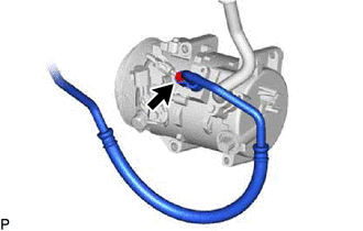
(b) Remove the O-ring from the No. 1 cooler refrigerant discharge hose sub-assembly.
NOTICE:
Seal the openings of the disconnected parts using vinyl tape to prevent moisture and foreign matter from entering them.
5. DISCONNECT SUCTION HOSE SUB-ASSEMBLY
| (a) Remove the bolt and disconnect the suction hose sub-assembly from the compressor assembly with magnetic clutch. |
|
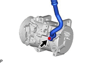
(b) Remove the O-ring from the suction hose sub-assembly.
NOTICE:
Seal the openings of the disconnected parts using vinyl tape to prevent moisture and foreign matter from entering them.
6. REMOVE COMPRESSOR ASSEMBLY WITH MAGNETIC CLUTCH
| (a) Disconnect each connector. |
|
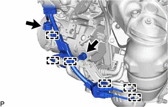
(b) Disengage each clamp.
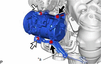
(c) for Type A:
(1) Remove the 2 bolts and 2 nuts, and separate the bracket.
|
*a | Bracket |
.png) |
Bolt |
.png) |
Nut |
| (2) Using an E8 "TORX" socket wrench, remove the 2 stud bolts. |
|
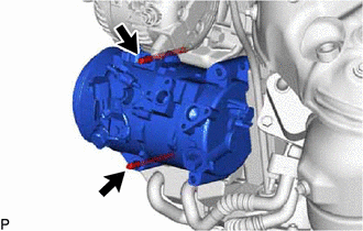
(d) for Type B:
| (1) Remove the 4 bolts and separate the bracket. |
|
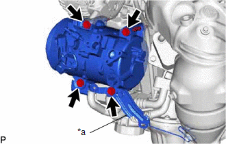
(e) Remove the compressor assembly with magnetic clutch.
READ NEXT:
 Disassembly
DISASSEMBLY PROCEDURE 1. REMOVE COOLER COMPRESSOR BRACKET
(a) Disengage the clamp.
(b) Remove the screw and cooler compressor bracket. 2. REMOVE MAGNET CLUTCH ASSEMBLY
(a) Se
Inspection
INSPECTION PROCEDURE 1. INSPECT MAGNET CLUTCH ASSEMBLY
*a Component without harness connected (Magnet Clutch Assembly)
(a) Measure the resistance according to the value(s) in the table b
Reassembly
REASSEMBLY PROCEDURE 1. INSTALL MAGNET CLUTCH ASSEMBLY
(a) Secure the cooler compressor assembly in a vise between aluminum plates.
(b) Install the magnet clutch stator with the parts aligned as
SEE MORE:
Right Front Wheel Speed Sensor Signal Stuck High (C050624)
DESCRIPTION Refer to DTC C050612 Click here
DTC No. Detection Item
DTC Detection Condition Trouble Area
C050624 Right Front Wheel Speed Sensor Signal Stuck High
The speed sensor signal is not within the specified range for 5 seconds or more.
Front speed senso
Reassembly
REASSEMBLY CAUTION / NOTICE / HINT
NOTICE: Steps 10 to 17 are temporary reassembly procedures for adjustment purposes. PROCEDURE
1. INSTALL STRAIGHT PIN (a) Using a plastic-faced hammer, install the 4 straight pins to the rear differential carrier sub-assembly.
*a 8.0 to 9.0 mm (0.3
