
Toyota Camry (XV70): Replacement
REPLACEMENT
PROCEDURE
1. RECOVER REFRIGERANT FROM REFRIGERATION SYSTEM
(a) Start the engine.
(b) Operate the compressor under the following conditions:
|
Item | Condition |
|---|---|
|
Operating Time | 3 minutes or more |
|
Temperature setting | Max cold |
|
Blower speed | High |
|
Engine | Idling |
|
A/C switch | On |
This causes most of the compressor oil from the various components of the A/C system to collect in the compressor.
HINT:
It is not necessary to operate the compressor if the A/C does not operate because of compressor lock, etc.
(c) Stop the engine.
(d) Recover the refrigerant from the A/C system using a refrigerant recovery unit.
HINT:
Use the refrigerant recovery unit in accordance with the manufacturer's instruction manual.
2. CHARGE AIR CONDITIONING SYSTEM WITH REFRIGERANT
HINT:
Charge refrigerant in accordance with the equipment manual.
(a) Perform vacuum purging using a vacuum pump or appropriate equipment.
NOTICE:
Be sure to use a refrigerant recovery unit that is compatible with HFO-1234yf (R1234yf) systems.
(b) Charge the air conditioning system with refrigerant.
Refrigerant Type:
HFO-1234yf (R1234yf)
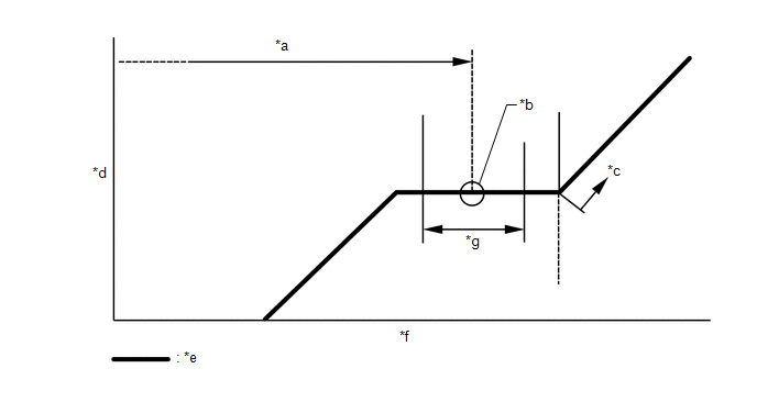
|
*a | Standard Charge Amount |
*b | Mean Value in Proper Range |
|
*c | Overcharged |
*d | High Pressure |
|
*e | Sub-cool System |
*f | Refrigerant Amount |
|
*g | +/-30 g (+/-1.05 oz) |
- | - |
Standard Charge Amount:
580 to 640 g (20.5 to 22.5 oz)
NOTICE:
- Do not turn the A/C switch on before charging the air conditioning system with refrigerant. Doing so may cause the compressor to operate without refrigerant, resulting in overheating of the compressor.
- The refrigerant amount should be checked by quantity (weight).
- The graph above is shown for reference only.
HINT:
Ensure that sufficient refrigerant is available to recharge the system when using a refrigerant recovery unit. Refrigerant recovery units are not always able to recover 100% of the refrigerant from an air conditioning system.
3. WARM UP ENGINE
(a) Keep the A/C switch on for at least 2 minutes to warm up the compressor.
NOTICE:
To prevent damage to the compressor, be sure to warm up the compressor when turning the air conditioning on after removing and installing any air conditioning system lines (including the compressor).
4. INSPECT FOR REFRIGERANT LEAK
(a) After recharging the air conditioning system with refrigerant, inspect for refrigerant leaks using a halogen leak detector.
HINT:
Be sure to use a halogen leak detector that is compatible with HFO-1234yf (R1234yf) systems.
(b) Carry out the test under the following conditions:
- Turn the engine switch off.
- Ensure good ventilation (the halogen leak detector may react to volatile gases which are not refrigerant, such as gasoline vapor and exhaust gas).
- Repeat the inspection 2 or 3 times.
- Measure the pressure to make sure that there is some refrigerant remaining in the air conditioning system.
Pressure when the compressor is off: approximately 392 to 588 kPa (3.9 to 5.9 kgf/cm2, 57 to 85 psi)
| (c) Using a halogen leak detector, inspect for refrigerant leaks from the air conditioning system. |
|
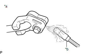
| (d) Bring the halogen leak detector close to the drain cooler hose with the detector power off, and then turn the detector on. HINT:
|
|
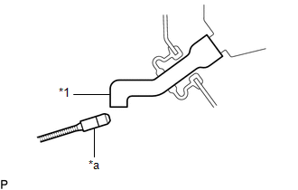
(e) If a refrigerant leak is not detected from the drain cooler hose, remove the blower motor control from the cooling unit. Insert the halogen leak detector sensor into the unit and check for leaks.
(f) Disconnect the pressure sensor connector and leave it for approximately 20 minutes. Bring the halogen leak detector close to the pressure sensor and check for leaks.
HINT:
When checking for leaks, the presence of oily dirt at a joint can indicate a leak.
READ NEXT:
 Components
COMPONENTS ILLUSTRATION
*A for A25A-FKS
- -
*1 PIPING CLAMP
*2 SUCTION PIPE SUB-ASSEMBLY
*3 SUCTION HOSE SUB-ASSEMBLY
*4 NO. 1 COOLER REFRIGERANT DISCHA
Removal
REMOVAL PROCEDURE 1. RECOVER REFRIGERANT FROM REFRIGERATION SYSTEM
Click here 2. REMOVE PIPING CLAMP (for Suction Hose Sub-assembly Side)
(a) for A25A-FKS: (1) While pressing the end of the suctio
SEE MORE:
Problem Symptoms Table
PROBLEM SYMPTOMS TABLE
HINT:
Use the table below to help determine the cause of problem symptoms. If multiple suspected areas are listed, the potential causes of the symptoms are listed in order of probability in the "Suspected Area" column of the table. Check each symptom by checking the susp
Rear Side Marker Light Bulb
ComponentsCOMPONENTS ILLUSTRATION
*1 REAR COMBINATION LIGHT ASSEMBLY
*2 REAR COMBINATION LIGHT COVER
*3 REAR SIDE MARKER LIGHT BULB
- - RemovalREMOVAL CAUTION / NOTICE / HINT
HINT:
Use the same procedure for the RH side and LH side.
The following pr
