Toyota Camry (XV70): Reverse Signal Circuit
DESCRIPTION
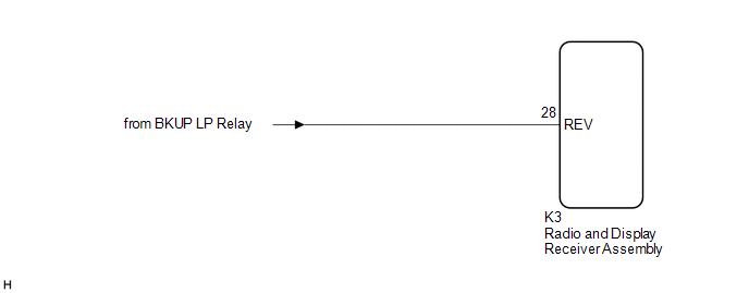
The radio and display receiver assembly receives a reverse signal from the BKUP LP relay.
WIRING DIAGRAM
PROCEDURE
| 1. |
CHECK BACK-UP LIGHT |
(a) Move the shift lever to R and check if the back-up lights come on.
OK:
The back-up lights come on.
| NG | .gif) | GO TO LIGHTING SYSTEM
|
.gif)
|
.gif)
| 2. |
CHECK HARNESS AND CONNECTOR (REVERSE SIGNAL) |
(a) Disconnect the K3 radio and display receiver assembly connector.
(b) Measure the voltage according to the value(s) in the table below.
Standard Voltage:
|
Tester Connection | Condition |
Specified Condition |
|---|---|---|
|
K3-28 (REV) - Body ground |
Ignition switch ON Shift lever in R |
11 to 14 V |
|
K3-28 (REV) - Body ground |
Ignition switch ON Shift lever not in R |
Below 1 V |
| OK | | PROCEED TO NEXT SUSPECTED AREA SHOWN IN PROBLEM SYMPTOMS TABLE
|
| NG | | REPAIR OR REPLACE HARNESS OR CONNECTOR |
READ NEXT:
 Voice Guidance Circuit between Radio Receiver and Stereo Component Amplifier
DESCRIPTION Using this circuit, the radio and display receiver assembly sends signals to the stereo component amplifier assembly. WIRING DIAGRAM
PROCEDURE
1.
CHECK HARNESS AND CONNECTOR
Microphone Circuit between Microphone and Radio Receiver
DESCRIPTION
w/o Manual (SOS) Switch:
The radio and display receiver assembly, roof console box sub-assembly and telephone microphone assembly are connected to each other using the microphone co
Radio Receiver Power Source Circuit
DESCRIPTION This is the power source circuit to operate the radio and display receiver assembly. WIRING DIAGRAM
CAUTION / NOTICE / HINT
NOTICE: Inspect the fuses for circuits related to this syst
SEE MORE:
Open in Bus 1 Main Bus Line
DESCRIPTION There may be an open circuit in one of the CAN main bus lines when the resistance between terminals 23 (CA1H) and 8 (CA1L) of the central gateway ECU (network gateway ECU) is 70 Ω or higher.
Symptom Trouble Area
Resistance between terminals 23 (CA1H) and 8 (CA1L) of
Installation
INSTALLATION CAUTION / NOTICE / HINT
HINT: When installing the name plates or luggage compartment door emblem, heat the luggage compartment door panel and name plates using a heat light. Heating Temperature
Item Temperature
Luggage Compartment Door Panel
40 to 60
