Toyota Camry (XV70): Voice Guidance Circuit between Radio Receiver and Stereo Component Amplifier
DESCRIPTION
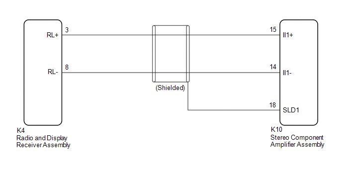
Using this circuit, the radio and display receiver assembly sends signals to the stereo component amplifier assembly.
WIRING DIAGRAM
PROCEDURE
| 1. |
CHECK HARNESS AND CONNECTOR (RADIO AND DISPLAY RECEIVER ASSEMBLY - STEREO COMPONENT AMPLIFIER ASSEMBLY) |
(a) Disconnect the K4 radio and display receiver assembly connector.
(b) Disconnect the K10 stereo component amplifier assembly connector.
(c) Measure the resistance according to the value(s) in the table below.
Standard Resistance:
|
Tester connection | Condition |
Specified condition |
|---|---|---|
|
K4-3 (RL+) - K10-15 (II1+) |
Always | Below 1 Ω |
|
K4-8 (RL-) - K10-14 (II1-) |
Always | Below 1 Ω |
|
K10-18 (SLD1) - Body ground |
Always | 10 kΩ or higher |
|
K4-3 (RL+) or K10-15 (II1+) - Body ground |
Always | 10 kΩ or higher |
|
K4-8 (RL-) or K10-14 (II1-) - Body ground |
Always | 10 kΩ or higher |
| OK | .gif) | PROCEED TO NEXT SUSPECTED AREA SHOWN IN PROBLEM SYMPTOMS TABLE
|
.gif)
| NG | | REPAIR OR REPLACE HARNESS OR CONNECTOR |
READ NEXT:
 Microphone Circuit between Microphone and Radio Receiver
DESCRIPTION
w/o Manual (SOS) Switch:
The radio and display receiver assembly, roof console box sub-assembly and telephone microphone assembly are connected to each other using the microphone co
Radio Receiver Power Source Circuit
DESCRIPTION This is the power source circuit to operate the radio and display receiver assembly. WIRING DIAGRAM
CAUTION / NOTICE / HINT
NOTICE: Inspect the fuses for circuits related to this syst
SEE MORE:
Installation
INSTALLATION CAUTION / NOTICE / HINT
HINT:
Use the same procedure for the RH side and LH side.
The following procedure is for the LH side.
PROCEDURE 1. INSTALL FRONT NO. 1 SPEAKER ASSEMBLY
NOTICE: Do not touch the speaker cone. (a) Connect the connector.
(b) Engage the 2 guides to
Components
COMPONENTS ILLUSTRATION
*1 REAR DISC BRAKE ANTI-SQUEAL SHIM KIT
*2 REAR DISC BRAKE PAD
*3 REAR DISC BRAKE CYLINDER ASSEMBLY
*4 REAR DISC BRAKE PAD WEAR INDICATOR PLATE
*5 REAR NO. 1 DISC BRAKE ANTI-SQUEAL SHIM
*6 REAR FLEXIBLE HOSE
