Toyota Camry (XV70): Rocker Panel Moulding
Components
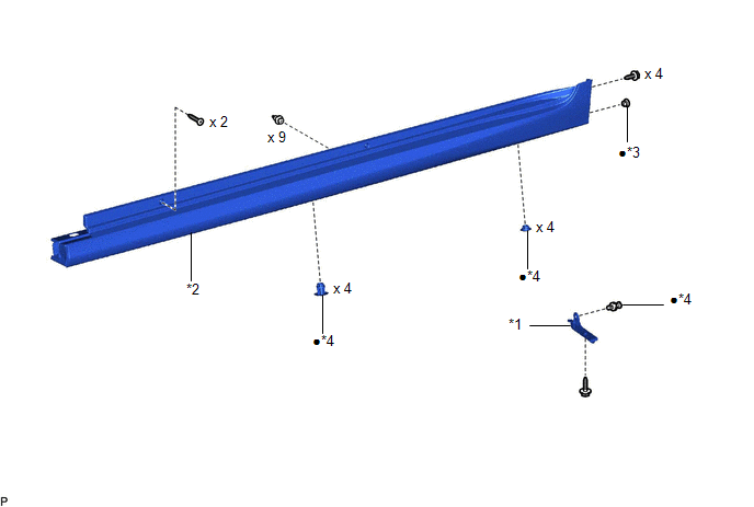
COMPONENTS
ILLUSTRATION
|
*1 | FRONT ROCKER PANEL MOULDING END COVER |
*2 | ROCKER PANEL MOULDING |
|
*3 | GROMMET |
*4 | CLIP |
|
● | Non-reusable part |
- | - |
Removal
REMOVAL
CAUTION / NOTICE / HINT
HINT:
- Use the same procedure for the RH side and LH side.
- The following procedure is for the LH side.
PROCEDURE
1. REMOVE FRONT ROCKER PANEL MOULDING END COVER
Click here .gif)
2. REMOVE ROCKER PANEL MOULDING
(a) Apply protective tape around the rocker panel moulding and doors as shown in the illustration.

.png) |
Protective Tape | - |
- |
(b) Remove the 8 clips.
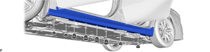
(c) Remove the 6 screws.
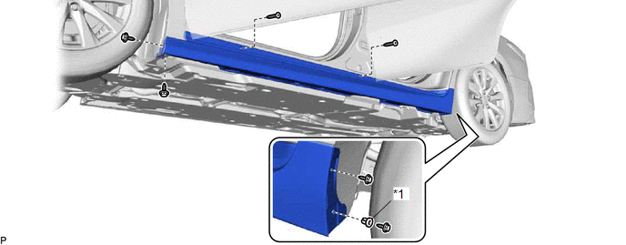
|
*1 | Grommet |
- | - |
(d) Remove the grommet
(e) Disengage the 9 clips to remove the rocker panel moulding as shown in the illustration.
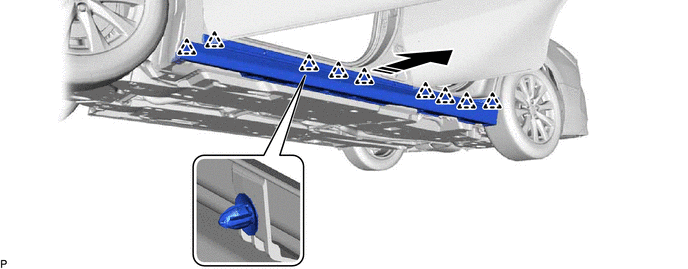
.png) |
Remove in this Direction |
- | - |
Installation
INSTALLATION
CAUTION / NOTICE / HINT
HINT:
- Use the same procedure for the RH side and LH side.
- The following procedure is for the LH side.
PROCEDURE
1. INSTALL ROCKER PANEL MOULDING
(a) Engage the 9 clips as shown in the illustration.

.png) |
Install in this Direction |
- | - |
(b) Install a new grommet.
(c) Install the 6 screws.
(d) Install the rocker panel moulding with 8 new clips.
2. INSTALL FRONT ROCKER PANEL MOULDING END COVER
Click here
.gif)
READ NEXT:
 Roof Drip Side Finish Moulding
ComponentsCOMPONENTS ILLUSTRATION
*1 ROOF DRIP SIDE FINISH MOULDING
*2 ROOF DRIP SIDE FINISH MOULDING CLIP
● Non-reusable part
- - RemovalREMOVAL C
Components
COMPONENTS ILLUSTRATION
*1 FRONT FENDER TO COWL SIDE SEAL
*2 NO. 1 WINDSHIELD OUTSIDE MOULDING CLIP
*3 NO. 3 WINDSHIELD OUTSIDE MOULDING CLIP
*4 WINDSHIELD
SEE MORE:
Tire Pressure Monitor ECU Communication Stop Mode
DESCRIPTION
Detection Item Symptom
Trouble Area Tire Pressure Monitor ECU Communication Stop Mode
Any of the following conditions are met:
Communication stop for "Tire Pressure" is indicated on the "Communication Bus Check" screen of the Techstream.
Click here
Cooling Fan Circuit
DESCRIPTION The ECM calculates an appropriate cooling fan speed based on the engine coolant temperature, air conditioning switch status, refrigerant pressure, engine speed and vehicle speed, and sends a signal to the cooling fan ECU (fan with motor assembly). The cooling fan ECU (fan with motor asse
