Toyota Camry (XV70): Tire Pressure Monitor ECU Communication Stop Mode
DESCRIPTION
|
Detection Item | Symptom |
Trouble Area |
|---|---|---|
| Tire Pressure Monitor ECU Communication Stop Mode |
Any of the following conditions are met:
|
|
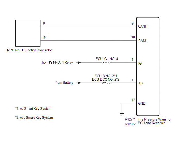
WIRING DIAGRAM
CAUTION / NOTICE / HINT
CAUTION:
When performing the confirmation driving pattern, obey all speed limits and traffic laws.
NOTICE:
- Because the order of diagnosis is important to allow correct diagnosis, make sure to begin troubleshooting using How to Proceed with Troubleshooting when CAN communication system related DTCs are output.
Click here
.gif)
- Before measuring the resistance of the CAN bus, turn the ignition switch off and leave the vehicle for 1 minute or more without operating the key or any switches, or opening or closing the doors. After that, disconnect the cable from the negative (-) battery terminal and leave the vehicle for 1 minute or more before measuring the resistance.
- After turning the ignition switch off, waiting time may be required before disconnecting the cable from the negative (-) battery terminal. Therefore, make sure to read the disconnecting the cable from the negative (-) battery terminal notices before proceeding with work.
Click here
- After performing repairs, perform the DTC check procedure and confirm that the DTCs are not output again.
DTC check procedure: Turn the ignition switch to ON and wait for 1 minute or more. Then operate the suspected malfunctioning system and drive the vehicle at 60 km/h (37 mph) or more for 5 minutes or more.
- After the repair, perform the CAN bus check and check that all the ECUs and sensors connected to the CAN communication system are displayed as normal.
Click here
- Inspect the fuses for circuits related to this system before performing the following procedure.
HINT:
- Before disconnecting related connectors for inspection, push in on each connector body to check that the connector is not loose or disconnected.
- When a connector is disconnected, check that the terminals and connector body are not cracked, deformed or corroded.
PROCEDURE
|
1. | CHECK VEHICLE TYPE |
(a) Check vehicle type.
|
Result | Proceed to |
|---|---|
|
w/ Smart Key System | A |
|
w/o Smart Key System |
B |
| B |
.gif) | GO TO STEP 4 |
|
.gif)
| 2. |
CHECK FOR OPEN IN CAN BUS LINES (TIRE PRESSURE WARNING ECU AND RECEIVER BRANCH LINE) |
(a) Disconnect the cable from the negative (-) battery terminal.
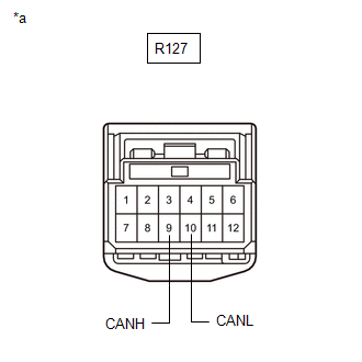
(b) Disconnect the R127 tire pressure warning ECU and receiver connector.
| (c) Measure the resistance according to the value(s) in the table below. Standard Resistance:
|
|
| NG | | REPAIR OR REPLACE CAN BRANCH LINES OR CONNECTOR (TIRE PRESSURE WARNING ECU AND RECEIVER) |
|
| 3. |
CHECK HARNESS AND CONNECTOR (POWER SOURCE CIRCUIT) |
| (a) Measure the resistance according to the value(s) in the table below. Standard Resistance:
|
|

(b) Reconnect the cable to the negative (-) battery terminal.
(c) Measure the voltage according to the value(s) in the table below.
Standard Voltage:
|
Tester Connection | Condition |
Specified Condition |
|---|---|---|
|
R127-1 (IG) - Body ground |
Ignition switch ON | 11 to 14 V |
|
R127-7 (+B) - Body ground |
Always | 11 to 14 V |
| OK | | REPLACE TIRE PRESSURE WARNING ECU AND RECEIVER |
| NG | | REPAIR OR REPLACE HARNESS OR CONNECTOR (POWER SOURCE CIRCUIT) |
| 4. |
CHECK FOR OPEN IN CAN BUS LINES (TIRE PRESSURE WARNING ECU AND RECEIVER BRANCH LINE) |
(a) Disconnect the cable from the negative (-) battery terminal.
(b) Disconnect the R128 tire pressure warning ECU and receiver connector.
| (c) Measure the resistance according to the value(s) in the table below. Standard Resistance:
|
|
.png)
| NG | | REPAIR OR REPLACE CAN BRANCH LINES OR CONNECTOR (TIRE PRESSURE WARNING ECU AND RECEIVER) |
|
| 5. |
CHECK HARNESS AND CONNECTOR (POWER SOURCE CIRCUIT) |
| (a) Measure the resistance according to the value(s) in the table below. Standard Resistance:
|
|

(b) Reconnect the cable to the negative (-) battery terminal.
(c) Measure the voltage according to the value(s) in the table below.
Standard Voltage:
|
Tester Connection | Condition |
Specified Condition |
|---|---|---|
|
R128-1 (IG) - Body ground |
Ignition switch ON | 11 to 14 V |
|
R128-7 (+B) - Body ground |
Always | 11 to 14 V |
| OK | | REPLACE TIRE PRESSURE WARNING ECU AND RECEIVER |
| NG | | REPAIR OR REPLACE HARNESS OR CONNECTOR (POWER SOURCE CIRCUIT) |
READ NEXT:
 Precaution
PRECAUTION PRECAUTION FOR DISCONNECTING CABLE FROM NEGATIVE BATTERY TERMINAL
NOTICE: When disconnecting the cable from the negative (-) battery terminal, initialize the following systems after the c
Parts Location
PARTS LOCATION ILLUSTRATION
*1 MULTIPLEX NETWORK MASTER SWITCH ASSEMBLY
*2 INSTRUMENT PANEL JUNCTION BLOCK ASSEMBLY
- ECU-B NO. 2 FUSE - DOOR F/L FUSE - DOOR F/R FUSE - DOOR R/L
SEE MORE:
Components
COMPONENTS ILLUSTRATION
*1 IGNITION COIL ASSEMBLY
*2 SPARK PLUG
*3 V-BANK COVER SUB-ASSEMBLY
*4 VACUUM HOSE
N*m (kgf*cm, ft.*lbf): Specified torque
- -
Reassembly
REASSEMBLY PROCEDURE 1. INSTALL BRAKE MASTER CYLINDER RESERVOIR STRAINER
2. INSTALL BRAKE MASTER CYLINDER RESERVOIR FILLER CAP ASSEMBLY 3. INSTALL MASTER CYLINDER RESERVOIR GROMMET
(a) Apply a light layer of lithium soap base glycol grease to the entire circumference of 2 new master cylinder res
