Toyota Camry (XV70): Sliding Roof does not Move by Operating Sliding Roof Control Switch
DESCRIPTION
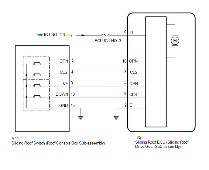
The sliding roof ECU (sliding roof drive gear sub-assembly) receives slide and tilt signals and operates its built-in motor when the sliding roof switch (roof console box sub-assembly) is operated.
WIRING DIAGRAM
CAUTION / NOTICE / HINT
NOTICE:
- Inspect the fuses for circuits related to this system before performing the following procedure.
- If the sliding roof ECU (sliding roof drive gear sub-assembly) is removed and reinstalled or replaced, the sliding roof ECU (sliding roof drive gear sub-assembly) must be initialized.
Click here
.gif)
- If a sliding roof ECU (sliding roof drive gear sub-assembly) DTC is output, first perform troubleshooting for the sliding roof ECU (sliding roof drive gear sub-assembly) DTC.
Click here
PROCEDURE
|
1. | PERFORM ACTIVE TEST USING TECHSTREAM (SLIDE ROOF) |
(a) Connect the Techstream to the DLC3.
(b) Turn the ignition switch to ON.
(c) Turn the Techstream on.
(d) Enter the following menus: Body Electrical / Slide Roof / Active Test.
(e) Perform the Active Test according to the display on the Techstream.
Body Electrical > Sliding Roof > Active Test|
Tester Display | Measurement Item |
Control Range | Diagnostic Note |
|---|---|---|---|
|
Slide Roof | Operate sliding roof motor |
OFF / Opn/Dwn / Clos/Up |
- |
|
Tester Display |
|---|
|
Slide Roof |
OK:
Slide roof is operated using Techstream.
| NG | .gif) |
REPLACE SLIDING ROOF ECU (SLIDING ROOF DRIVE GEAR SUB-ASSEMBLY)
|
|
.gif)
|
2. | READ VALUE USING TECHSTREAM |
(a) Enter the following menus: Body Electrical / Sliding Roof / Data List.
(b) Read the Data List according to the display on the Techstream.
Body Electrical > Sliding Roof > Data List|
Tester Display | Measurement Item |
Range | Normal Condition |
Diagnostic Note |
|---|---|---|---|---|
|
Open Switch | OPEN switch signal |
OFF or ON | OFF: OPEN switch not pressed ON: OPEN switch pressed |
- |
| Close Switch |
CLOSE switch signal |
OFF or ON | OFF: CLOSE switch not pressed ON: CLOSE switch pressed |
- |
| Up Switch |
UP switch signal |
OFF or ON | OFF: UP switch not pressed ON: UP switch pressed |
- |
| Down Switch |
DOWN switch signal |
OFF or ON | OFF: DOWN switch not pressed ON: DOWN switch pressed |
- |
|
Tester Display |
|---|
|
Open Switch |
|
Close Switch |
|
Up Switch |
|
Down Switch |
OK:
The Techstream display changes according to the operation of each switch as shown in the table.
| OK | |
REPLACE SLIDING ROOF ECU (SLIDING ROOF DRIVE GEAR SUB-ASSEMBLY)
|
|
|
3. | INSPECT SLIDING ROOF SWITCH (ROOF CONSOLE BOX SUB-ASSEMBLY) |
(a) Remove the sliding roof switch (roof console box sub-assembly).
Click here
(b) Inspect the sliding roof switch (roof console box sub-assembly).
Click here
| NG | |
REPLACE SLIDING ROOF SWITCH (ROOF CONSOLE BOX SUB-ASSEMBLY)
|
|
|
4. | CHECK HARNESS AND CONNECTOR (SLIDING ROOF ECU (SLIDING ROOF DRIVE GEAR SUB-ASSEMBLY) - IG POWER SUPPLY AND BODY GROUND) |
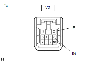
| (a) Disconnect the V2 sliding roof ECU (sliding roof drive gear sub-assembly) connector. |
|
(b) Measure the voltage according to the value(s) in the table below.
Standard Voltage:
|
Tester Connection | Condition |
Specified Condition |
|---|---|---|
|
V2-6 (IG) - Body ground |
Ignition switch ON |
11 to 14 V |
|
V2-6 (IG) - Body ground |
Ignition switch off |
Below 1 V |
(c) Measure the resistance according to the value(s) in the table below.
Standard Resistance:
|
Tester Connection | Condition |
Specified Condition |
|---|---|---|
|
V2-2 (E) - Body ground |
Always | Below 1 Ω |
| NG | |
REPAIR OR REPLACE HARNESS OR CONNECTOR |
|
|
5. | CHECK HARNESS AND CONNECTOR (SLIDING ROOF ECU (SLIDING ROOF DRIVE GEAR SUB-ASSEMBLY) - SLIDING ROOF SWITCH (ROOF CONSOLE BOX SUB-ASSEMBLY) AND BODY GROUND) |
(a) Disconnect the V14 sliding roof switch (roof console box sub-assembly) connector.
(b) Disconnect the V2 sliding roof ECU (sliding roof drive gear sub-assembly) connector.
(c) Measure the resistance according to the value(s) in the table below.
Standard Resistance:
|
Tester Connection | Condition |
Specified Condition |
|---|---|---|
|
V2-8 (CLS) - V14-4 (CLS) |
Always | Below 1 Ω |
|
V2-8 (CLS) or V14-4 (CLS) - Body ground |
Always | 10 kΩ or higher |
|
V2-10 (OPN) - V14-5 (OPN) |
Always | Below 1 Ω |
|
V2-10 (OPN) or V14-5 (OPN) - Body ground |
Always | 10 kΩ or higher |
|
V2-9 (CLS) - V14-18 (DOWN) |
Always | Below 1 Ω |
|
V2-9 (CLS) or V14-18 (DOWN) - Body ground |
Always | 10 kΩ or higher |
|
V2-5 (OPN) - V14-3 (UP) |
Always | Below 1 Ω |
|
V2-5 (OPN) or V14-3 (UP) - Body ground |
Always | 10 kΩ or higher |
|
V14-15 (GND) - Body ground |
Always | Below 1 Ω |
|
V2-2 (E) - Body ground |
Always | Below 1 Ω |
| OK | |
REPLACE SLIDING ROOF ECU (SLIDING ROOF DRIVE GEAR SUB-ASSEMBLY)
|
| NG | |
REPAIR OR REPLACE HARNESS OR CONNECTOR |
READ NEXT:
 Components
COMPONENTS ILLUSTRATION
*1 PACKAGE TRAY TRIM PANEL ASSEMBLY
*2 REAR SEAT OUTER BELT ASSEMBLY LH
*3 REAR SEAT OUTER BELT ASSEMBLY RH
*4 REAR SEAT SHOULDER BE
SEE MORE:
Parts Location
PARTS LOCATION ILLUSTRATION
*1 FORWARD RECOGNITION CAMERA
*2 MILLIMETER WAVE RADAR SENSOR ASSEMBLY
*3 SKID CONTROL ECU (BRAKE ACTUATOR ASSEMBLY)
*4 ECM ILLUSTRATION
*1 COMBINATION METER ASSEMBLY
*2 AIRBAG SENSOR ASSEMBLY
*3 MAIN
Inspection
INSPECTION PROCEDURE 1. INSPECT FUEL INJECTOR ASSEMBLY
(a) Check the resistance.
(1) Measure the resistance according to the value(s) in the table below.
Standard Resistance:
Tester Connection Condition
Specified Condition 1 - 2
20°C (68°F) 11.6 to 12.4 ]
