Toyota Camry (XV70): Starting System
Toyota Camry Repair Manual XV70 (2018-2024) / Engine, Hybrid System / 2gr-fks (starting) / Starting System
Parts Location
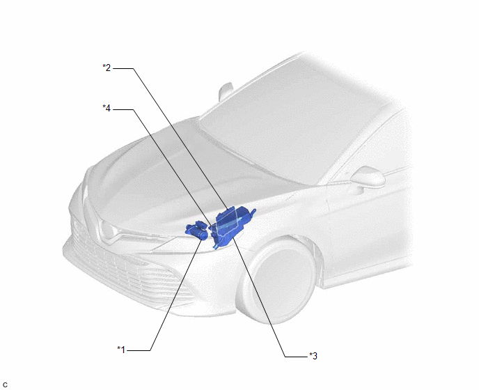
PARTS LOCATION
ILLUSTRATION
|
*1 | STARTER ASSEMBLY |
*2 | ECM |
|
*3 | ENGINE ROOM RELAY BLOCK AND JUNCTION BLOCK ASSEMBLY - ST RELAY - FL MAIN FUSE - ST FUSE |
*4 | PARK/NEUTRAL POSITION SWITCH ASSEMBLY |
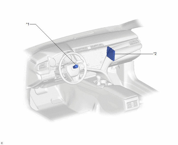
ILLUSTRATION
|
*1 | ENGINE SWITCH |
*2 | CERTIFICATION ECU (SMART KEY ECU ASSEMBLY) |
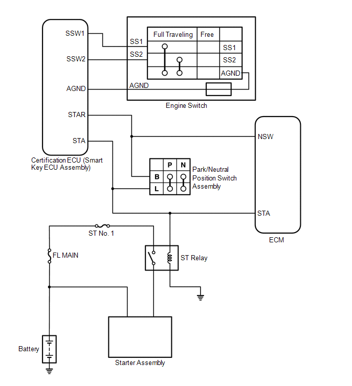
System Diagram
SYSTEM DIAGRAM
Parts Location
PARTS LOCATION
ILLUSTRATION
.png)
|
*1 | STARTER ASSEMBLY |
*2 | ECM |
|
*3 | ENGINE ROOM RELAY BLOCK AND JUNCTION BLOCK ASSEMBLY - ST RELAY - FL MAIN FUSE - ST FUSE |
*4 | PARK/NEUTRAL POSITION SWITCH ASSEMBLY |
ILLUSTRATION
.png)
|
*1 | ENGINE SWITCH |
*2 | CERTIFICATION ECU (SMART KEY ECU ASSEMBLY) |
System Diagram
SYSTEM DIAGRAM
.png)
READ NEXT:
 Coolant
ComponentsCOMPONENTS ILLUSTRATION
*1 RADIATOR CAP SUB-ASSEMBLY
*2 RADIATOR DRAIN COCK PLUG
*3 NO. 1 ENGINE UNDER COVER
- - ReplacementREPLACEMENT CAUTION / NOT
SEE MORE:
Components
COMPONENTS ILLUSTRATION
*1 NO. 2 ENGINE UNDER COVER ASSEMBLY
*2 V-RIBBED BELT
*3 FRONT WHEEL OPENING EXTENSION PAD LH
*4 FRONT WHEEL OPENING EXTENSION PAD RH
*5 NO. 1 ENGINE UNDER COVER
- -
N*m (kgf*cm, ft.*lbf): Specified torque
Lost Communication with Meter (B1324,B1325)
DESCRIPTION These DTCs are stored when communication between the radio and display receiver assembly and combination meter assembly or headup display (meter mirror sub-assembly)* is not possible.
DTC No. Detection Item
DTC Detection Condition Trouble Area
B1324 Lost Communic
© 2023-2026 Copyright www.tocamry.com
