Toyota Camry (XV70): Steering Angle Sensor Supply Voltage Circuit Circuit Short to Ground or Open (C14FE14)
DESCRIPTION
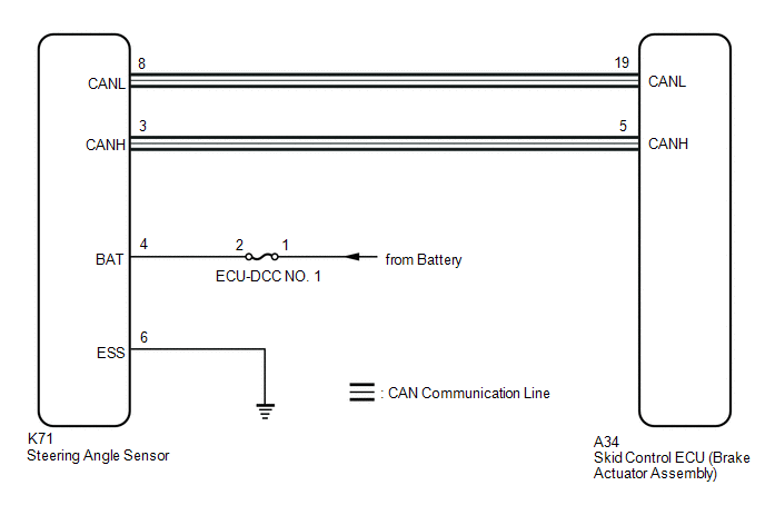
This DTC is stored when the skid control ECU (brake actuator assembly) receives a +B line open signal from the steering angle sensor.
|
DTC No. | Detection Item |
DTC Detection Condition | Trouble Area |
|---|---|---|---|
|
C14FE14 | Steering Angle Sensor Supply Voltage Circuit Circuit Short to Ground or Open |
With the +BS terminal voltage between 9.6 and 16.5 V, a steering angle sensor power supply circuit malfunction signal is received from the steering angle sensor. |
|
WIRING DIAGRAM
CAUTION / NOTICE / HINT
NOTICE:
Inspect the fuses for circuits related to this system before performing the following procedure.
PROCEDURE
| 1. |
CLEAR DTC |
(a) Connect the Techstream to the DLC3.
(b) Turn the ignition switch to ON.
(c) Operate the Techstream to clear the codes. Enter the following menus: Chassis / Brake/EPB / Trouble Codes.
Chassis > Brake > Clear DTCs(d) Press the DTC clear button.
|
.gif)
| 2. |
RECONFIRM DTC |
(a) Connect the Techstream to the DLC3.
(b) Start the engine.
(c) Perform a road test under the same malfunction conditions recreated based on the Freeze Frame Data or customer problem analysis.
(d) Read the DTCs following the prompts on the Techstream. Enter the following menus: Chassis / Brake/EPB / Trouble Codes.
Chassis > Brake > Trouble Codes(e) Check if the same DTC is output.
|
Result | Proceed to |
|---|---|
|
C14FE14 is not output |
A |
| C14FE14 is output |
B |
| A |
.gif) | USE SIMULATION METHOD TO CHECK
|
.gif)
|
| 3. |
CHECK HARNESS AND CONNECTOR (POWER SOURCE TERMINAL) |
| (a) Remove the steering wheel and column cover. |
|
(b) Make sure that there is no looseness at the locking part and the connecting part of the connector.
OK:
The connector is securely connected.
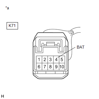
(c) Disconnect the K71 steering angle sensor connector.
(d) Check both the connector case and the terminals for deformation and corrosion.
OK:
No deformation or corrosion.
(e) Measure the voltage according to the value(s) in the table below.
Standard Voltage:
|
Tester Connection | Condition |
Specified Condition |
|---|---|---|
|
K71-4 (BAT) - Body ground |
Always | 11 to 14 V |
| OK | | REPLACE STEERING ANGLE SENSOR |
| NG | | REPAIR OR REPLACE HARNESS OR CONNECTOR |
READ NEXT:
 Brake Switch "A" Circuit Short to Ground (P057111)
DESCRIPTION The skid control ECU (brake actuator assembly) receives stop light switch assembly signals and uses them to determine whether or not the brakes are applied.
When the brake pedal is depre
Brake Switch "A" Circuit Short to Battery (P057112)
DESCRIPTION The skid control ECU (brake actuator assembly) receives stop light switch assembly signals and uses them to determine whether or not the brakes are applied.
DTCs may be stored if either
Brake Switch "A" Circuit Open (P057113)
DESCRIPTION The skid control ECU (brake actuator assembly) receives stop light switch assembly signals and uses them to determine whether or not the brakes are applied.
The skid control ECU (brake a
SEE MORE:
Components
COMPONENTS ILLUSTRATION
*1 AIR CLEANER CAP WITH AIR CLEANER HOSE
*2 ENGINE COOLANT TEMPERATURE SENSOR
*3 VACUUM HOSE
*4 NO. 1 FUEL VAPOR FEED HOSE
*5 NO. 2 VENTILATION HOSE
- -
O2 Sensor Slow Response - Rich to Lean Bank 1 Sensor 1 (P014C00-P014F00,P015A00-P015D00)
DESCRIPTION Refer to DTC P219519. Click here
HINT: Although the DTC titles say oxygen sensor, these DTCs relate to the air fuel ratio sensor.
DTC No. Detection Item
DTC Detection Condition Trouble Area
MIL Memory
Note P014C00
O2 Sensor Slow Response - Rich to
