Toyota Camry (XV70): System Diagram
Toyota Camry Repair Manual XV70 (2018-2024) / Engine, Hybrid System / 2gr-fks (engine Control) / Sfi System / System Diagram
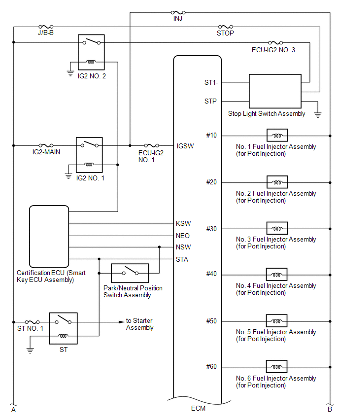
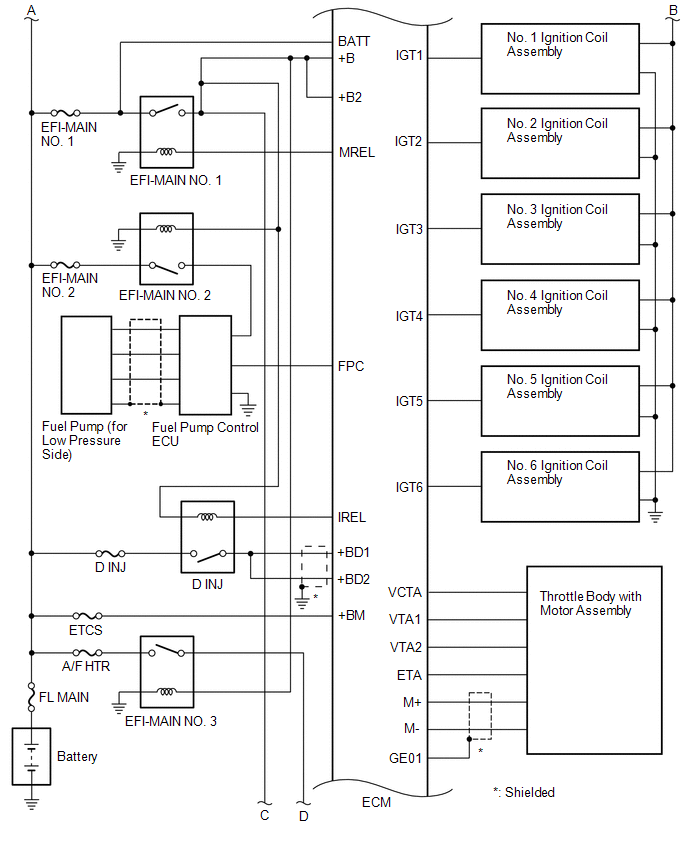
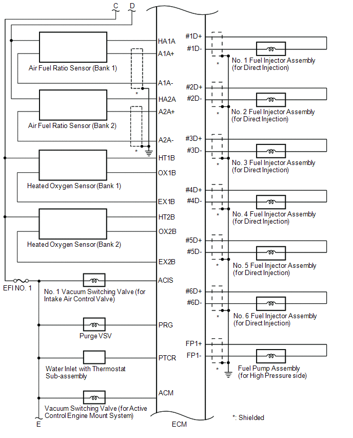
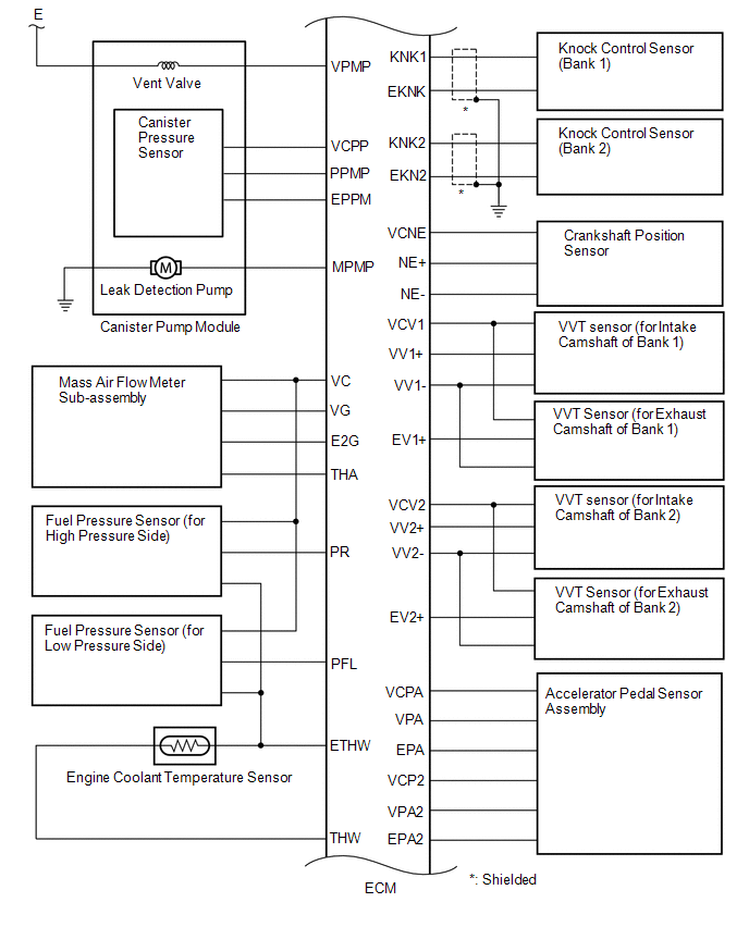
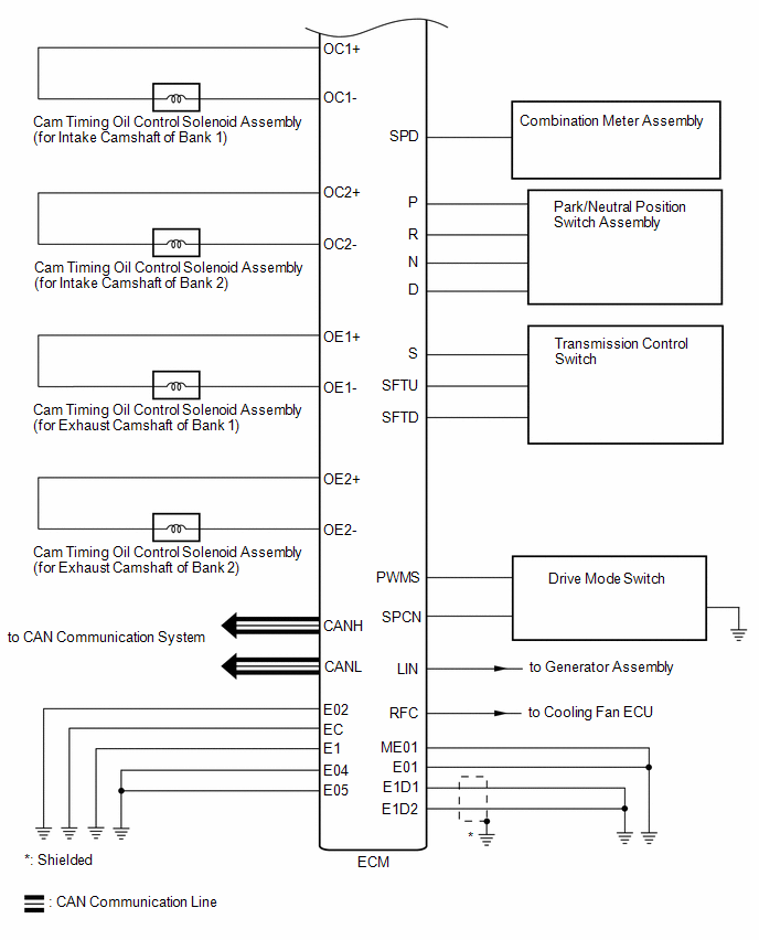
SYSTEM DIAGRAM
READ NEXT:
 How To Proceed With Troubleshooting
CAUTION / NOTICE / HINT HINT: *: Use the Techstream. PROCEDURE
1.
VEHICLE BROUGHT TO WORKSHOP
NEXT
2.
CUSTOMER PROBLEM ANALYSIS
Check For Intermittent Problems
CHECK FOR INTERMITTENT PROBLEMS HINT: Inspect the vehicle ECM using check mode. Intermittent problems are easier to detect with the Techstream when the ECM is in check mode. In check mode, the ECM use
Basic Inspection
CAUTION / NOTICE / HINT When a malfunction is not confirmed by the DTC check, troubleshooting should be carried out for all circuits considered to be possible causes of the problem. In many cases, by
SEE MORE:
Voice Guidance does not Function
CAUTION / NOTICE / HINT
NOTICE:
Depending on the parts that are replaced during vehicle inspection or maintenance, performing initialization, registration or calibration may be needed. Refer to Precaution for Audio and Visual System.
Click here
When replacing the radio and display
Components
COMPONENTS ILLUSTRATION
*1 ENGINE ASSEMBLY WITH TRANSAXLE
*2 FRONT BUMPER EXTENSION SUB-ASSEMBLY RH
*3 FRONT BUMPER EXTENSION SUB-ASSEMBLY LH
*4 FRONT SUSPENSION MEMBER BRACKET SUB-ASSEMBLY RH
*5 FRONT SUSPENSION MEMBER BRACKET SUB-ASSEMBLY LH
*6
© 2023-2026 Copyright www.tocamry.com
