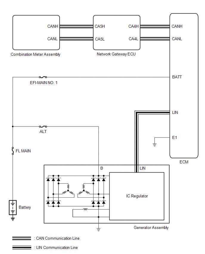
Toyota Camry (XV70): System Diagram
SYSTEM DIAGRAM

READ NEXT:
 How To Proceed With Troubleshooting
CAUTION / NOTICE / HINT HINT: *: Use the Techstream. PROCEDURE
1.
VEHICLE BROUGHT TO WORKSHOP
NEXT
2.
CUSTOMER PROBLEM ANALYSIS
HINT:
In
 Problem Symptoms Table
PROBLEM SYMPTOMS TABLE
HINT:
Use the table below to help determine the cause of problem symptoms. If multiple suspected areas are listed, the potential causes of the symptoms are listed in order
 Terminals Of Ecm
TERMINALS OF ECM
HINT: The standard normal voltage and resistance between each pair of ECM terminals is shown in the table below. The appropriate conditions for checking each pair of terminals are
SEE MORE:
 Removal
REMOVAL CAUTION / NOTICE / HINT
The necessary procedures (adjustment, calibration, initialization or registration) that must be performed after parts are removed and installed, or replaced during vacuum warning switch assembly removal/installation are shown below. Necessary Procedures After Parts
 Components
COMPONENTS ILLUSTRATION
*A for TMC made
- -
*1 NO. 1 ENGINE UNDER COVER
*2 NO. 2 ENGINE UNDER COVER ASSEMBLY
*3 FRONT WHEEL OPENING EXTENSION PAD LH
*4 FRONT WHEEL OPENING EXTENSION PAD RH
*5 FRONT FENDER APRON SEAL LH
- -
© 2023-2026 Copyright www.tocamry.com

