
Toyota Camry (XV70): System Diagram
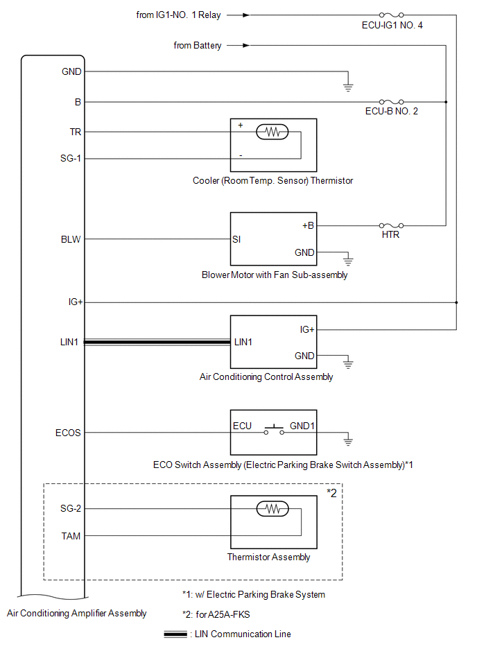
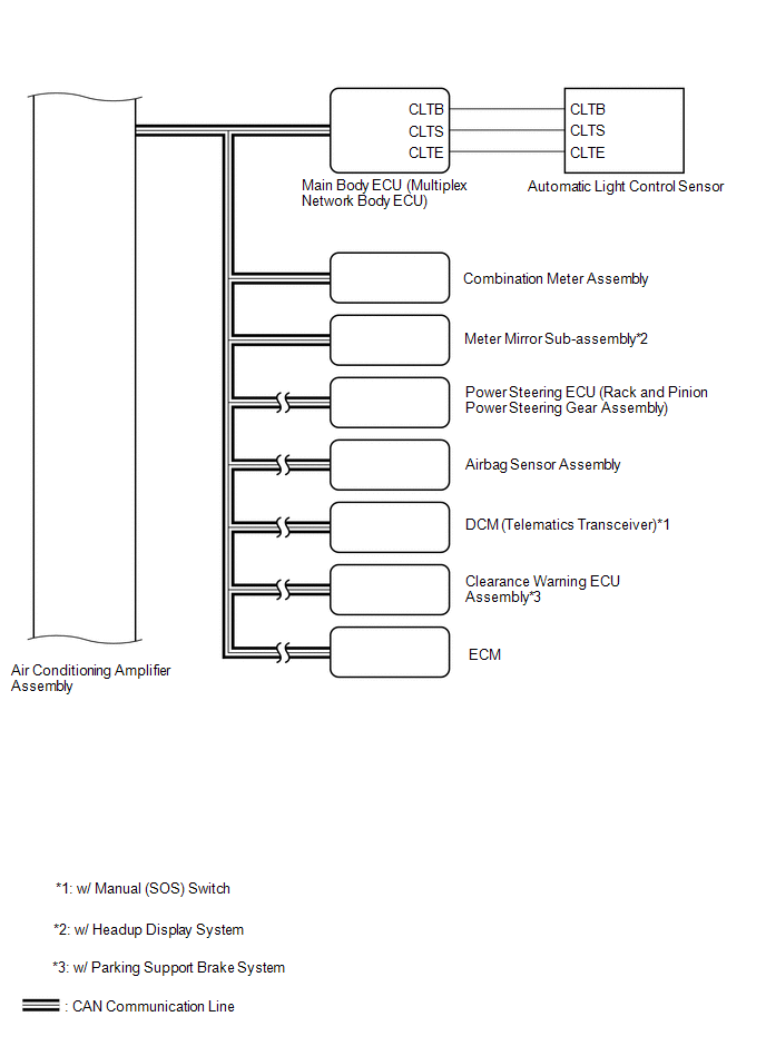
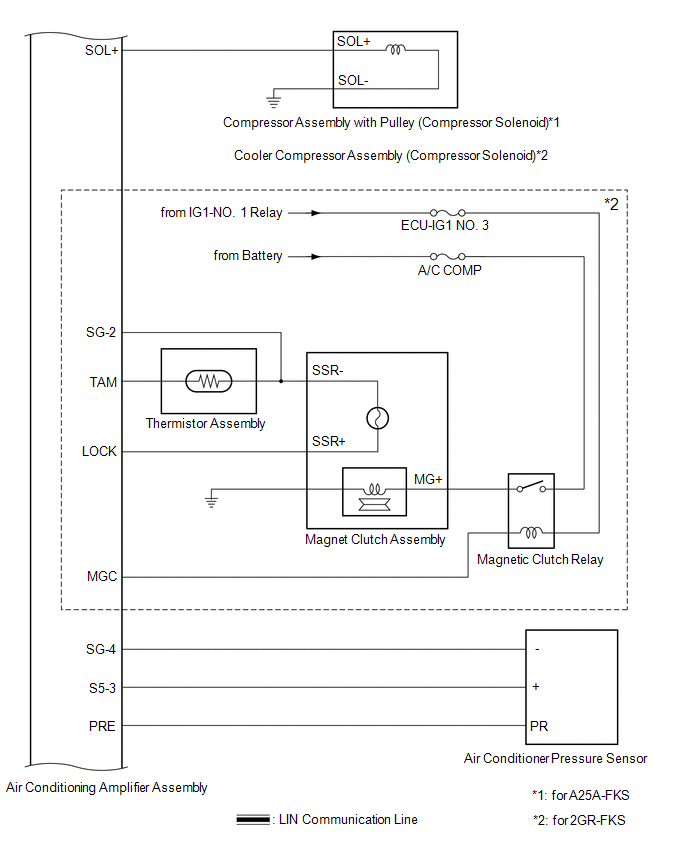
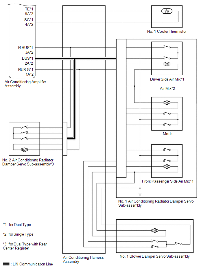
SYSTEM DIAGRAM
READ NEXT:
 System Description
SYSTEM DESCRIPTION COMMUNICATION SYSTEM FUNCTION
(a) The air conditioning amplifier assembly communicates with each ECU via CAN communication and LIN communication. Additionally, the air conditioning
How To Proceed With Troubleshooting
CAUTION / NOTICE / HINT
HINT:
Use the following procedure to troubleshoot the air conditioning system.
*: Use the Techstream.
PROCEDURE
1. VEHICLE BROUGHT TO WORKSHOP
NEX
Customize Parameters
CUSTOMIZE PARAMETERS CUSTOMIZE AIR CONDITIONING SYSTEM (for Automatic Air Conditioning System)
(a) Customizing with the Techstream.
NOTICE:
When the customer requests a change in a function, first
SEE MORE:
Parts Location
PARTS LOCATION ILLUSTRATION
*1 FORWARD RECOGNITION CAMERA
*2 MILLIMETER WAVE RADAR SENSOR ASSEMBLY
*3 SKID CONTROL ECU (BRAKE ACTUATOR ASSEMBLY)
*4 POWER STEERING ECU (RACK AND PINION POWER STEERING GEAR ASSEMBLY)
*5 ECM
- - ILLUSTRATION
Inspection
INSPECTION PROCEDURE 1. INSPECT FUEL PUMP
(a) Measure the resistance according to the value(s) in the table below.
Standard Resistance:
Tester Connection Specified Condition
U - V 0.05 to 3.0 Ω
V - W 0.05 to 3.0 Ω
U - W 0.05 to 3.0 Ω
© 2023-2026 Copyright www.tocamry.com
