Toyota Camry (XV70): Terminals Of Ecu
TERMINALS OF ECU
NOTICE:
- After turning the ignition switch off, waiting time may be required before disconnecting the cable from the negative (-) battery terminal. Therefore, make sure to read the disconnecting the cable from the negative (-) battery terminal notices before proceeding with work.
Click here
.gif)
- Before measuring the resistance of the CAN bus, turn the ignition switch off and leave the vehicle for 1 minute or more without operating the key or any switches, or opening or closing the doors. After that, disconnect the cable from the negative (-) battery terminal and leave the vehicle for 1 minute or more before measuring the resistance.
- This section describes the standard values for all CAN related components.
HINT:
- The systems (ECUs and sensors) that use CAN communication vary depending on the vehicle and optional equipment. Check which systems (ECUs and sensors) are installed to the vehicle.
Click here
- Operating the ignition switch, any other switches or a door triggers related ECU and sensor communication on the CAN. This communication will cause the resistance value to change.
- Even after DTCs are cleared, if a DTC is stored again after driving the vehicle for a while, the malfunction may be occurring due to vibration of the vehicle. In such a case, wiggling the ECUs or wire harness while performing the inspection below may help determine the cause of the malfunction.
NO. 1 CAN JUNCTION CONNECTOR
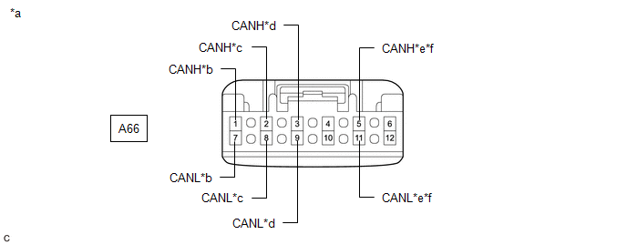
(a) Check the No. 1 CAN junction connector.
(1) Connection diagram
|
*a | Front view of wire harness connector (to No. 1 CAN Junction Connector) |
*b | to Millimeter Wave Radar Sensor Assembly (w/ Front Camera System) |
|
*c | to Forward Recognition Camera (w/ Front Camera System) |
*d | to Central Gateway ECU (Network Gateway ECU) |
|
*e | to No. 5 CAN Junction Connector (w/ Parking Assist Monitor System or Panoramic View Monitor System) |
*f | to Central Gateway ECU (Network Gateway ECU) (w/ Rear View Monitor System) |
(2) Check the connection diagram of the components which are connected to the No. 1 CAN junction connector.
|
Terminal No. (Symbol) | Wiring Color |
Connected to |
|---|---|---|
| A66-1 (CANH) |
R | Millimeter wave radar sensor assembly*1 (for Bus 1) |
|
A66-7 (CANL) | W | |
|
A66-2 (CANH) | G |
Forward recognition camera*1 (for Bus 1) |
|
A66-8 (CANL) | W | |
|
A66-3 (CANH) | P |
Central gateway ECU (network gateway ECU) (for Bus 1) |
|
A66-9 (CANL) | W | |
|
A66-5 (CANH) | B |
No. 5 CAN junction connector*2 (for Bus 1) |
|
A66-11 (CANL) | W | |
|
A66-5 (CANH) | B |
Central gateway ECU (network gateway ECU)*3 (for Bus 1) |
|
A66-11 (CANL) | W |
- *1: w/ Front Camera System
- *2: w/ Parking Assist Monitor System or Panoramic View Monitor System
- *3: w/ Rear View Monitor System
NO. 2 CAN JUNCTION CONNECTOR
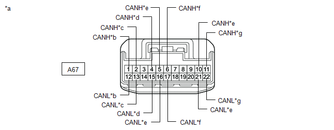
(a) Check the No. 2 CAN junction connector.
(1) Connection diagram
|
*a | Front view of wire harness connector (to No. 2 CAN Junction Connector) |
*b | to Brake Actuator Assembly |
|
*c | to No. 3 Junction Connector |
*d | to Rack and Pinion Power Steering Gear Assembly |
|
*e | to No. 4 CAN Junction Connector |
*f | to 4WD ECU Assembly (for AWD) |
|
*g | to ECM |
- | - |
(2) Check the connection diagram of the components which are connected to the No. 2 CAN junction connector.
|
Terminal No. (Symbol) | Wiring Color |
Connected to |
|---|---|---|
| A67-1 (CANH) |
Y | Brake actuator assembly (for Bus 4) |
|
A67-12 (CANL) | W | |
|
A67-2 (CANH) | R |
No. 3 junction connector (for Bus 4) |
|
A67-13 (CANL) | W | |
|
A67-4 (CANH) | G |
Rack and pinion power steering gear assembly (for Bus 4) |
|
A67-15 (CANL) | W | |
|
A67-5 (CANH) | GR |
No. 4 CAN junction connector (for Bus 4) |
|
A67-16 (CANL) | W | |
|
A67-6 (CANH) | P |
4WD ECU assembly* (for Bus 4) |
|
A67-17 (CANL) | W | |
|
A67-10 (CANH) | L |
No. 4 CAN junction connector (for Bus 2) |
|
A67-21 (CANL) | W | |
|
A67-11 (CANH) | B |
ECM (for Bus 2) |
|
A67-22 (CANL) | W |
- *: for AWD
NO. 3 CAN JUNCTION CONNECTOR
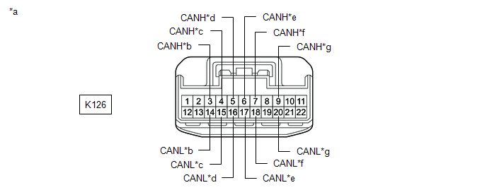
(a) Check the No. 3 CAN junction connector.
(1) Connection diagram
|
*a | Front view of wire harness connector (to No. 3 CAN Junction Connector) |
*b | to No. 1 Junction Connector |
|
*c | to Certification ECU (Smart Key ECU Assembly) (w/ Smart Key System) |
*d | to Combination Meter Assembly |
|
*e | to Main Body ECU (Multiplex Network Body ECU) |
*f | to Air Conditioning Amplifier Assembly |
|
*g | to Meter Mirror Sub-assembly (w/ Headup Display System) |
- | - |
(2) Check the connection diagram of the components which are connected to the No. 3 CAN junction connector.
|
Terminal No. (Symbol) | Wiring Color |
Connected to |
|---|---|---|
| K126-3 (CANH) |
P | No. 1 junction connector (for Bus 5) |
|
K126-14 (CANL) | W | |
|
K126-4 (CANH) | G |
Certification ECU (smart key ECU assembly)*1 (for Bus 5) |
|
K126-15 (CANL) | W | |
|
K126-5 (CANH) | B |
Combination meter assembly (for Bus 5) |
|
K126-16 (CANL) | W | |
|
K126-6 (CANH) | BE |
Main body ECU (multiplex network body ECU) (for Bus 5) |
|
K126-17 (CANL) | W | |
|
K126-7 (CANH) | SB |
Air conditioning amplifier assembly (for Bus 5) |
|
K126-18 (CANL) | W | |
|
K126-9 (CANH) | LG |
Meter mirror sub-assembly*2 (for Bus 5) |
|
K126-20 (CANL) | W |
- *1: w/ Smart Key System
- *2: w/ Headup Display System
NO. 4 CAN JUNCTION CONNECTOR
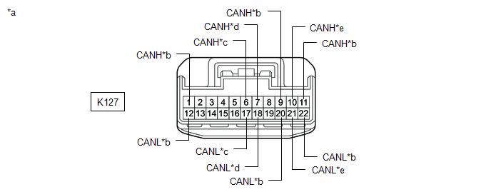
(a) Check the No. 4 CAN junction connector.
(1) Connection diagram
|
*a | Front view of wire harness connector (to No. 4 CAN Junction Connector) |
*b | to Central Gateway ECU (Network Gateway ECU) |
|
*c | to No. 2 CAN Junction Connector |
*d | to Steering Sensor |
|
*e | to DCM (Telematics Transceiver) (w/ Telematics Transceiver) |
- | - |
(2) Check the connection diagram of the components which are connected to the No. 4 CAN junction connector.
|
Terminal No. (Symbol) | Wiring Color |
Connected to |
|---|---|---|
| K127-1 (CANH) |
SB | Central gateway ECU (network gateway ECU) (for Bus 2) |
|
K127-12 (CANL) | W | |
|
K127-6 (CANH) | SB |
No. 2 CAN junction connector (for Bus 4) |
|
K127-17 (CANL) | W | |
|
K127-7 (CANH) | G |
Steering sensor (for Bus 4) |
|
K127-18 (CANL) | W | |
|
K127-9 (CANH) | L |
Central gateway ECU (network gateway ECU) (for Bus 3) |
|
K127-20 (CANL) | W | |
|
K127-10 (CANH) | R |
DCM (telematics transceiver)* (for Bus 3) |
|
K127-21 (CANL) | W | |
|
K127-11 (CANH) | GR |
Central gateway ECU (network gateway ECU) (for Bus 3) |
|
K127-22 (CANL) | W |
- *: w/ Telematics Transceiver
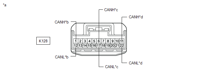
(b) Check the No. 4 CAN junction connector.
(1) Connection diagram
|
*a | Front view of wire harness connector (to No. 4 CAN Junction Connector) |
*b | to Radio and Display Receiver Assembly |
|
*c | to Airbag Sensor Assembly |
*d | to No. 2 CAN Junction Connector |
(2) Check the connection diagram of the components which are connected to the No. 4 CAN junction connector.
|
Terminal No. (Symbol) | Wiring Color |
Connected to |
|---|---|---|
| K128-1 (CANH) |
B | Radio and display receiver assembly (for Bus 3) |
|
K128-12 (CANL) | W | |
|
K128-6 (CANH) | R |
Airbag sensor assembly (for Bus 4) |
|
K128-17 (CANL) | W | |
|
K128-11 (CANH) | G |
No. 2 CAN junction connector (for Bus 2) |
|
K128-22 (CANL) | W |
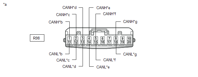
NO. 5 CAN JUNCTION CONNECTOR (w/ Parking Assist Monitor System or Panoramic View Monitor System)
(a) Check the No. 5 CAN junction connector.
(1) Connection diagram
|
*a | Front view of wire harness connector (to No. 5 CAN Junction Connector) |
*b | to Central Gateway ECU (Network Gateway ECU) |
|
*c | to Clearance Warning ECU Assembly (w/ Intuitive Parking Assist System) |
*d | to Blind Spot Monitor Sensor RH (w/ Blind Spot Monitor System) |
|
*e | to Rear Television Camera Assembly |
*f | to No. 1 CAN Junction Connector |
|
*g | to Television Camera Controller (w/ Panoramic View Monitor System) |
- | - |
(2) Check the connection diagram of the components which are connected to the No. 5 CAN junction connector.
|
Terminal No. (Symbol) | Wiring Color |
Connected to |
|---|---|---|
| R98-1 (CANH) |
GR | Central gateway ECU (network gateway ECU) (for Bus 1) |
|
R98-11 (CANL) | W | |
|
R98-2 (CANH) | L |
Clearance warning ECU assembly*1 (for Bus 1) |
|
R98-12 (CANL) | W | |
|
R98-3 (CANH) | BE |
Blind spot monitor sensor RH*2 (for Bus 1) |
|
R98-13 (CANL) | W | |
|
R98-4 (CANH) | R |
Rear television camera assembly (for Bus 1) |
|
R98-14 (CANL) | W | |
|
R98-5 (CANH) | B |
No. 1 CAN junction connector (for Bus 1) |
|
R98-15 (CANL) | W | |
|
R98-8 (CANH) | GR |
Television camera controller*3 (for Bus 1) |
|
R98-18 (CANL) | W |
- *1: w/ Intuitive Parking Assist System
- *2: w/ Blind Spot Monitor System
- *3: w/ Panoramic View Monitor System
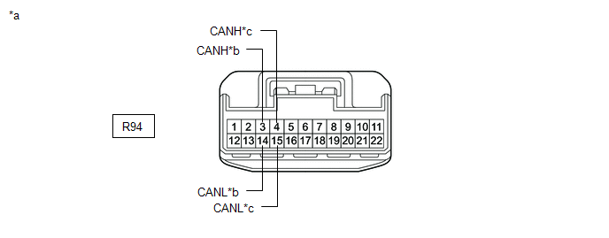
NO. 1 JUNCTION CONNECTOR
(a) Check the No. 1 junction connector.
(1) Connection diagram
|
*a | Front view of wire harness connector (to No. 1 Junction Connector) |
*b | to No. 3 CAN Junction Connector |
|
*c | to No. 2 Junction Connector |
- | - |
(2) Check the connection diagram of the components which are connected to the No. 1 junction connector.
|
Terminal No. (Symbol) | Wiring Color |
Connected to |
|---|---|---|
| R94-3 (CANH) |
B | No. 3 CAN junction connector (for Bus 5) |
|
R94-14 (CANL) | W | |
|
R94-4 (CANH) | L |
No. 2 junction connector (for Bus 5) |
|
R94-15 (CANL) | W |
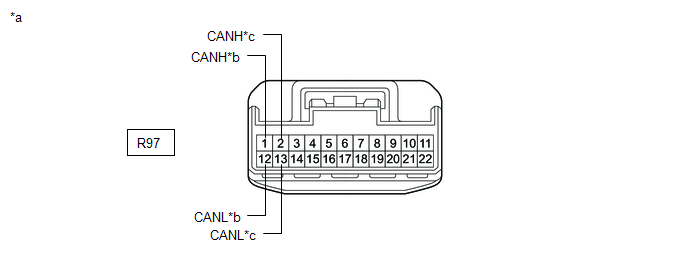
NO. 2 JUNCTION CONNECTOR
(a) Check the No. 2 junction connector.
(1) Connection diagram
|
*a | Front view of wire harness connector (to No. 2 Junction Connector) |
*b | to Central Gateway ECU (Network Gateway ECU) |
|
*c | to No. 1 Junction Connector |
- | - |
(2) Check the connection diagram of the components which are connected to the No. 2 junction connector.
|
Terminal No. (Symbol) | Wiring Color |
Connected to |
|---|---|---|
| R97-1 (CANH) |
G | Central gateway ECU (network gateway ECU) (for Bus 5) |
|
R97-12 (CANL) | W | |
|
R97-2 (CANH) | L |
No. 1 junction connector (for Bus 5) |
|
R97-13 (CANL) | W |
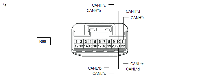
NO. 3 JUNCTION CONNECTOR
(a) Check the No. 3 junction connector.
(1) Connection diagram
|
*a | Front view of wire harness connector (to No. 3 Junction Connector) |
*b | to Tire Pressure Warning ECU and Receiver (for Tire Pressure Warning System with Tire Inflation Pressure Display Function) |
|
*c | to Occupant Detection ECU |
*d | to Central Gateway ECU (Network Gateway ECU) |
|
*e | to No. 2 CAN Junction Connector |
- | - |
(2) Check the connection diagram of the components which are connected to the No. 3 junction connector.
|
Terminal No. (Symbol) | Wiring Color |
Connected to |
|---|---|---|
| R99-8 (CANH) |
L | Tire pressure warning ECU and receiver* (for Bus 4) |
|
R99-19 (CANL) | W | |
|
R99-9 (CANH) | GR |
Occupant detection ECU (for Bus 4) |
|
R99-20 (CANL) | W | |
|
R99-10 (CANH) | G |
Central gateway ECU (network gateway ECU) (for Bus 4) |
|
R99-21 (CANL) | W | |
|
R99-11 (CANH) | LG |
No. 2 CAN junction connector (for Bus 4) |
|
R99-22 (CANL) | W |
- *: for Tire Pressure Warning System with Tire Inflation Pressure Display Function
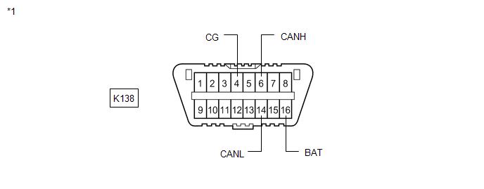
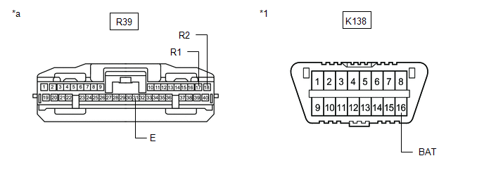
DLC3
(a) Disconnect the cable from the negative (-) battery terminal.
(b) Measure the resistance according to the value(s) in the table below.
|
*1 | DLC3 |
- | - |
Standard Resistance:
|
Terminal No. (Symbol) | Wiring Color |
Terminal Description | Condition |
Specified Condition |
|---|---|---|---|---|
|
K138-6 (CANH) - K138-14 (CANL) |
B - W | HIGH-level CAN bus line - LOW-level CAN bus line |
Cable disconnected from negative (-) battery terminal |
54 to 69 Ω |
|
K138-6 (CANH) - K138-4 (CG) |
B - W-B | HIGH-level CAN bus line - Ground |
Cable disconnected from negative (-) battery terminal |
200 Ω or higher |
|
K138-14 (CANL) - K138-4 (CG) |
W - W-B | LOW-level CAN bus line - Ground |
Cable disconnected from negative (-) battery terminal |
200 Ω or higher |
|
K138-6 (CANH) - K138-16 (BAT) |
B - R | HIGH-level CAN bus line - Battery positive (+) |
Cable disconnected from negative (-) battery terminal |
6 kΩ or higher |
|
K138-14 (CANL) - K138-16 (BAT) |
W - R | LOW-level CAN bus line - Battery positive (+) |
Cable disconnected from negative (-) battery terminal |
6 kΩ or higher |
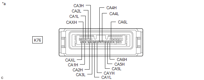
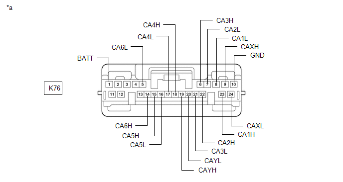
CENTRAL GATEWAY ECU (NETWORK GATEWAY ECU)
|
*a | Component without harness connected (Central Gateway ECU (Network Gateway ECU)) |
- | - |
(a) Disconnect the cable from the negative (-) battery terminal.
(b) Disconnect the K76 central gateway ECU (network gateway ECU) connector.
(c) Measure the resistance according to the value(s) in the table below.
|
*a | Front view of wire harness connector (to Central Gateway ECU (Network Gateway ECU)) |
- | - |
Standard Resistance:
Diagnosis Bus Branch Lines (DLC3 - Central gateway ECU (network gateway ECU))|
Terminal No. (Symbol) | Wiring Color |
Terminal Description | Condition |
Specified Condition |
|---|---|---|---|---|
|
K76-14 (CA6H) - K76-5 (CA6L) |
B - W | HIGH-level CAN bus line - LOW-level CAN bus line |
Cable disconnected from negative (-) battery terminal |
1 MΩ or higher |
|
K76-14 (CA6H) - K76-10 (GND) |
B - W-B | HIGH-level CAN bus line - Ground |
Cable disconnected from negative (-) battery terminal |
200 Ω or higher |
|
K76-5 (CA6L) - K76-10 (GND) |
W - W-B | LOW-level CAN bus line - Ground |
Cable disconnected from negative (-) battery terminal |
200 Ω or higher |
|
K76-14 (CA6H) - K76-1 (BATT) |
B - BE | HIGH-level CAN bus line - Battery positive (+) |
Cable disconnected from negative (-) battery terminal |
6 kΩ or higher |
|
K76-5 (CA6L) - K76-1 (BATT) |
W - BE | LOW-level CAN bus line - Battery positive (+) |
Cable disconnected from negative (-) battery terminal |
6 kΩ or higher |
|
Terminal No. (Symbol) | Wiring Color |
Terminal Description | Condition |
Specified Condition |
|---|---|---|---|---|
|
K76-23 (CA1H) - K76-9 (CAXH) |
B - BE | HIGH-level CAN bus line - HIGH-level CAN bus line |
Cable disconnected from negative (-) battery terminal |
Below 1 Ω |
|
K76-8 (CA1L) - K76-24 (CAXL) |
W - W | LOW-level CAN bus line - LOW-level CAN bus line |
Cable disconnected from negative (-) battery terminal |
Below 1 Ω |
|
K76-23 (CA1H) - K76-10 (GND) |
B - W-B | HIGH-level CAN bus line - Ground |
Cable disconnected from negative (-) battery terminal |
200 Ω or higher |
|
K76-8 (CA1L) - K76-10 (GND) |
W - W-B | LOW-level CAN bus line - Ground |
Cable disconnected from negative (-) battery terminal |
200 Ω or higher |
|
K76-23 (CA1H) - K76-1 (BATT) |
B - BE | HIGH-level CAN bus line - Battery positive (+) |
Cable disconnected from negative (-) battery terminal |
6 kΩ or higher |
|
K76-8 (CA1L) - K76-1 (BATT) |
W - BE | LOW-level CAN bus line - Battery positive (+) |
Cable disconnected from negative (-) battery terminal |
6 kΩ or higher |
|
Terminal No. (Symbol) | Wiring Color |
Terminal Description | Condition |
Specified Condition |
|---|---|---|---|---|
|
K76-18 (CA4H) - K76-17 (CA4L) |
SB - W | HIGH-level CAN bus line - LOW-level CAN bus line |
Cable disconnected from negative (-) battery terminal |
108 to 132 Ω |
|
K76-18 (CA4H) - K76-10 (GND) |
SB - W-B | HIGH-level CAN bus line - Ground |
Cable disconnected from negative (-) battery terminal |
200 Ω or higher |
|
K76-17 (CA4L) - K76-10 (GND) |
W - W-B | LOW-level CAN bus line - Ground |
Cable disconnected from negative (-) battery terminal |
200 Ω or higher |
|
K76-18 (CA4H) - K76-1 (BATT) |
SB - BE | HIGH-level CAN bus line - Battery positive (+) |
Cable disconnected from negative (-) battery terminal |
6 kΩ or higher |
|
K76-17 (CA4L) - K76-1 (BATT) |
W - BE | LOW-level CAN bus line - Battery positive (+) |
Cable disconnected from negative (-) battery terminal |
6 kΩ or higher |
|
Terminal No. (Symbol) | Wiring Color |
Terminal Description | Condition |
Specified Condition |
|---|---|---|---|---|
|
K76-6 (CA3H) - K76-19 (CAYH) |
L - GR | HIGH-level CAN bus line - HIGH-level CAN bus line |
Cable disconnected from negative (-) battery terminal |
Below 1 Ω |
|
K76-21 (CA3L) - K76-20 (CAYL) |
W - W | LOW-level CAN bus line - LOW-level CAN bus line |
Cable disconnected from negative (-) battery terminal |
Below 1 Ω |
|
K76-6 (CA3H) - K76-10 (GND) |
L - W-B | HIGH-level CAN bus line - Ground |
Cable disconnected from negative (-) battery terminal |
200 Ω or higher |
|
K76-21 (CA3L) - K76-10 (GND) |
W - W-B | LOW-level CAN bus line - Ground |
Cable disconnected from negative (-) battery terminal |
200 Ω or higher |
|
K76-6 (CA3H) - K76-1 (BATT) |
L - BE | HIGH-level CAN bus line - Battery positive (+) |
Cable disconnected from negative (-) battery terminal |
6 kΩ or higher |
|
K76-21 (CA3L) - K76-1 (BATT) |
W - BE | LOW-level CAN bus line - Battery positive (+) |
Cable disconnected from negative (-) battery terminal |
6 kΩ or higher |
|
Terminal No. (Symbol) | Wiring Color |
Terminal Description | Condition |
Specified Condition |
|---|---|---|---|---|
|
K76-22 (CA2H) - K76-7 (CA2L) |
G - W | HIGH-level CAN bus line - LOW-level CAN bus line |
Cable disconnected from negative (-) battery terminal |
108 to 132 Ω |
|
K76-22 (CA2H) - K76-10 (GND) |
G - W-B | HIGH-level CAN bus line - Ground |
Cable disconnected from negative (-) battery terminal |
200 Ω or higher |
|
K76-7 (CA2L) - K76-10 (GND) |
W - W-B | LOW-level CAN bus line - Ground |
Cable disconnected from negative (-) battery terminal |
200 Ω or higher |
|
K76-22 (CA2H) - K76-1 (BATT) |
G - BE | HIGH-level CAN bus line - Battery positive (+) |
Cable disconnected from negative (-) battery terminal |
6 kΩ or higher |
|
K76-7 (CA2L) - K76-1 (BATT) |
W - BE | LOW-level CAN bus line - Battery positive (+) |
Cable disconnected from negative (-) battery terminal |
6 kΩ or higher |
|
Terminal No. (Symbol) | Wiring Color |
Terminal Description | Condition |
Specified Condition |
|---|---|---|---|---|
|
K76-15 (CA5H) - K76-16 (CA5L) |
LG - W | HIGH-level CAN bus line - LOW-level CAN bus line |
Cable disconnected from negative (-) battery terminal |
108 to 132 Ω |
|
K76-15 (CA5H) - K76-10 (GND) |
LG - W-B | HIGH-level CAN bus line - Ground |
Cable disconnected from negative (-) battery terminal |
200 Ω or higher |
|
K76-16 (CA5L) - K76-10 (GND) |
W - W-B | LOW-level CAN bus line - Ground |
Cable disconnected from negative (-) battery terminal |
200 Ω or higher |
|
K76-15 (CA5H) - K76-1 (BATT) |
LG - BE | HIGH-level CAN bus line - Battery positive (+) |
Cable disconnected from negative (-) battery terminal |
6 kΩ or higher |
|
K76-16 (CA5L) - K76-1 (BATT) |
W - BE | LOW-level CAN bus line - Battery positive (+) |
Cable disconnected from negative (-) battery terminal |
6 kΩ or higher |
STEERING SENSOR
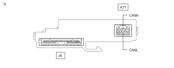
|
*a | Component without harness connected (Steering Sensor) | - |
- |
(a) Disconnect the cable from the negative (-) battery terminal.
(b) Disconnect the K71 steering sensor connector.
(c) Measure the resistance according to the value(s) in the table below.
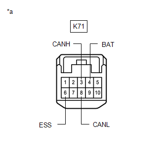
|
*a | Front view of wire harness connector (to Steering Sensor) |
Standard Resistance:
|
Terminal No. (Symbol) | Wiring Color |
Terminal Description | Condition |
Specified Condition |
|---|---|---|---|---|
|
K71-3 (CANH) - K71-8 (CANL) |
G - W | HIGH-level CAN bus line - LOW-level CAN bus line |
Cable disconnected from negative (-) battery terminal |
54 to 69 Ω |
|
K71-3 (CANH) - K71-6 (ESS) |
G - W-B | HIGH-level CAN bus line - Ground |
Cable disconnected from negative (-) battery terminal |
200 Ω or higher |
|
K71-8 (CANL) - K71-6 (ESS) |
W - W-B | LOW-level CAN bus line - Ground |
Cable disconnected from negative (-) battery terminal |
200 Ω or higher |
|
K71-3 (CANH) - K71-4 (BAT) |
G - GR | HIGH-level CAN bus line - Battery positive (+) |
Cable disconnected from negative (-) battery terminal |
6 kΩ or higher |
|
K71-8 (CANL) - K71-4 (BAT) |
W - GR | LOW-level CAN bus line - Battery positive (+) |
Cable disconnected from negative (-) battery terminal |
6 kΩ or higher |
ECM (for A25A-FKS)
Refer to Terminals of ECU.
Click here
(a) Disconnect the cable from the negative (-) battery terminal.
(b) Disconnect the A24 ECM connector.
(c) Measure the resistance according to the value(s) in the table below.
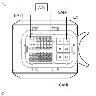
|
*a | Front view of wire harness connector (to ECM) |
Standard Resistance:
|
Terminal No. (Symbol) | Wiring Color |
Terminal Description | Condition |
Specified Condition |
|---|---|---|---|---|
|
A24-8 (CANH) - A24-18 (CANL) |
B - W | HIGH-level CAN bus line - LOW-level CAN bus line |
Cable disconnected from negative (-) battery terminal |
108 to 132 Ω |
|
A24-8 (CANH) - A24-10 (E1) |
B - W-B | HIGH-level CAN bus line - Ground |
Cable disconnected from negative (-) battery terminal |
200 Ω or higher |
|
A24-18 (CANL) - A24-10 (E1) |
W - W-B | LOW-level CAN bus line - Ground |
Cable disconnected from negative (-) battery terminal |
200 Ω or higher |
|
A24-8 (CANH) - A24-1 (BATT) |
B - G | HIGH-level CAN bus line - Battery positive (+) |
Cable disconnected from negative (-) battery terminal |
6 kΩ or higher |
|
A24-18 (CANL) - A24-1 (BATT) |
W - G | LOW-level CAN bus line - Battery positive (+) |
Cable disconnected from negative (-) battery terminal |
6 kΩ or higher |
ECM (for 2GR-FKS)
Refer to Terminals of ECU.
Click here
(a) Disconnect the cable from the negative (-) battery terminal.
(b) Disconnect the A21 and C96 ECM connectors.
(c) Measure the resistance according to the value(s) in the table below.
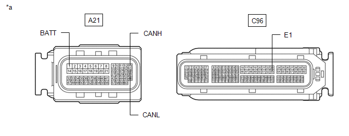
|
*a | Front view of wire harness connector (to ECM) | - |
- |
Standard Resistance:
|
Terminal No. (Symbol) | Wiring Color |
Terminal Description | Condition |
Specified Condition |
|---|---|---|---|---|
|
A21-13 (CANH) - A21-26 (CANL) |
B - W | HIGH-level CAN bus line - LOW-level CAN bus line |
Cable disconnected from negative (-) battery terminal |
108 to 132 Ω |
|
A21-13 (CANH) - C96-53 (E1) |
B - W-B | HIGH-level CAN bus line - Ground |
Cable disconnected from negative (-) battery terminal |
200 Ω or higher |
|
A21-26 (CANL) - C96-53 (E1) |
W - W-B | LOW-level CAN bus line - Ground |
Cable disconnected from negative (-) battery terminal |
200 Ω or higher |
|
A21-13 (CANH) - A21-1 (BATT) |
B - R | HIGH-level CAN bus line - Battery positive (+) |
Cable disconnected from negative (-) battery terminal |
6 kΩ or higher |
|
A21-26 (CANL) - A21-1 (BATT) |
W - R | LOW-level CAN bus line - Battery positive (+) |
Cable disconnected from negative (-) battery terminal |
6 kΩ or higher |
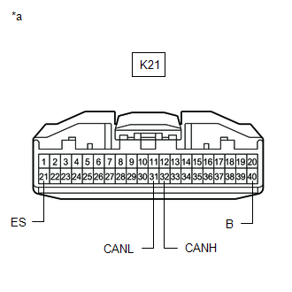
COMBINATION METER ASSEMBLY
Refer to Terminals of ECU.
Click here
(a) Disconnect the cable from the negative (-) battery terminal.
(b) Disconnect the K21 combination meter assembly connector.
(c) Measure the resistance according to the value(s) in the table below.
|
*a | Front view of wire harness connector (to Combination Meter Assembly) |
Standard Resistance:
|
Terminal No. (Symbol) | Wiring Color |
Terminal Description | Condition |
Specified Condition |
|---|---|---|---|---|
|
K21-32 (CANH) - K21-31 (CANL) |
B - W | HIGH-level CAN bus line - LOW-level CAN bus line |
Cable disconnected from negative (-) battery terminal |
108 to 132 Ω |
|
K21-32 (CANH) - K21-21 (ES) |
B - W-B | HIGH-level CAN bus line - Ground |
Cable disconnected from negative (-) battery terminal |
200 Ω or higher |
|
K21-31 (CANL) - K21-21 (ES) |
W - W-B | LOW-level CAN bus line - Ground |
Cable disconnected from negative (-) battery terminal |
200 Ω or higher |
|
K21-32 (CANH) - K21-40 (B) |
B - LA-B | HIGH-level CAN bus line - Battery positive (+) |
Cable disconnected from negative (-) battery terminal |
6 kΩ or higher |
|
K21-31 (CANL) - K21-40 (B) |
W - LA-B | LOW-level CAN bus line - Battery positive (+) |
Cable disconnected from negative (-) battery terminal |
6 kΩ or higher |
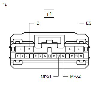
METER MIRROR SUB-ASSEMBLY (w/ Headup Display System)
Refer to Terminals of ECU.
Click here
(a) Disconnect the cable from the negative (-) battery terminal.
(b) Disconnect the p1 meter mirror sub-assembly connector.
(c) Measure the resistance according to the value(s) in the table below.
Standard Resistance:
|
Terminal No. (Symbol) | Wiring Color |
Terminal Description | Condition |
Specified Condition |
|---|---|---|---|---|
|
p1-12 (MPX1) - p1-13 (MPX2) |
P - R | HIGH-level CAN bus line - LOW-level CAN bus line |
Cable disconnected from negative (-) battery terminal |
54 to 69 Ω |
|
p1-12 (MPX1) - p1-4 (ES) |
P - W-B | HIGH-level CAN bus line - Ground |
Cable disconnected from negative (-) battery terminal |
200 Ω or higher |
|
p1-13 (MPX2) - p1-4 (ES) |
R - W-B | LOW-level CAN bus line - Ground |
Cable disconnected from negative (-) battery terminal |
200 Ω or higher |
|
p1-12 (MPX1) - p1-2 (B) |
P - P | HIGH-level CAN bus line - Battery positive (+) |
Cable disconnected from negative (-) battery terminal |
6 kΩ or higher |
|
p1-13 (MPX2) - p1-2 (B) |
R - P | LOW-level CAN bus line - Battery positive (+) |
Cable disconnected from negative (-) battery terminal |
6 kΩ or higher |
|
*a | Front view of wire harness connector (to Meter Mirror Sub-assembly) |
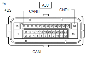
BRAKE ACTUATOR ASSEMBLY (w/o Electric Parking Brake System)
Refer to Terminals of ECU.
Click here
(a) Disconnect the cable from the negative (-) battery terminal.
(b) Disconnect the A33 brake actuator assembly connector.
(c) Measure the resistance according to the value(s) in the table below.
Standard Resistance:
|
Terminal No. (Symbol) | Wiring Color |
Terminal Description | Condition |
Specified Condition |
|---|---|---|---|---|
|
A33-26 (CANH) - A33-14 (CANL) |
Y - W | HIGH-level CAN bus line - LOW-level CAN bus line |
Cable disconnected from negative (-) battery terminal |
54 to 69 Ω |
|
A33-26 (CANH) - A33-38 (GND1) |
Y - W-B | HIGH-level CAN bus line - Ground |
Cable disconnected from negative (-) battery terminal |
200 Ω or higher |
|
A33-14 (CANL) - A33-38 (GND1) |
W - W-B | LOW-level CAN bus line - Ground |
Cable disconnected from negative (-) battery terminal |
200 Ω or higher |
|
A33-26 (CANH) - A33-25 (+BS) |
Y - L | HIGH-level CAN bus line - Battery positive (+) |
Cable disconnected from negative (-) battery terminal |
6 kΩ or higher |
|
A33-14 (CANL) - A33-25 (+BS) |
W - L | LOW-level CAN bus line - Battery positive (+) |
Cable disconnected from negative (-) battery terminal |
6 kΩ or higher |
|
*a | Front view of wire harness connector (to Brake Actuator Assembly) |
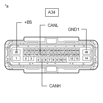
BRAKE ACTUATOR ASSEMBLY (w/ Electric Parking Brake System)
Refer to Terminals of ECU.
Click here
(a) Disconnect the cable from the negative (-) battery terminal.
(b) Disconnect the A34 brake actuator assembly connector.
(c) Measure the resistance according to the value(s) in the table below.
Standard Resistance:
|
Terminal No. (Symbol) | Wiring Color |
Terminal Description | Condition |
Specified Condition |
|---|---|---|---|---|
|
A34-5 (CANH) - A34-19 (CANL) |
Y - W | HIGH-level CAN bus line - LOW-level CAN bus line |
Cable disconnected from negative (-) battery terminal |
54 to 69 Ω |
|
A34-5 (CANH) - A34-46 (GND1) |
Y - W-B | HIGH-level CAN bus line - Ground |
Cable disconnected from negative (-) battery terminal |
200 Ω or higher |
|
A34-19 (CANL) - A34-46 (GND1) |
W - W-B | LOW-level CAN bus line - Ground |
Cable disconnected from negative (-) battery terminal |
200 Ω or higher |
|
A34-5 (CANH) - A34-30 (+BS) |
Y - G | HIGH-level CAN bus line - Battery positive (+) |
Cable disconnected from negative (-) battery terminal |
6 kΩ or higher |
|
A34-19 (CANL) - A34-30 (+BS) |
W - G | LOW-level CAN bus line - Battery positive (+) |
Cable disconnected from negative (-) battery terminal |
6 kΩ or higher |
|
*a | Front view of wire harness connector (to Brake Actuator Assembly) |
MAIN BODY ECU (MULTIPLEX NETWORK BODY ECU)
Refer to Terminals of ECU.
Click here
(a) Disconnect the cable from the negative (-) battery terminal.
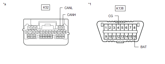
(b) Disconnect the K52 main body ECU (multiplex network body ECU) connector.
(c) Measure the resistance according to the value(s) in the table below.
|
*1 | DLC3 |
- | - |
|
*a | Front view of wire harness connector (to Main Body ECU (Multiplex Network Body ECU)) |
- | - |
Standard Resistance:
|
Terminal No. (Symbol) | Wiring Color |
Terminal Description | Condition |
Specified Condition |
|---|---|---|---|---|
|
K52-5 (CANH) - K52-4 (CANL) |
BE - W | HIGH-level CAN bus line - LOW-level CAN bus line |
Cable disconnected from negative (-) battery terminal |
54 to 69 Ω |
|
K52-5 (CANH) - K138-4 (CG) |
BE - W-B | HIGH-level CAN bus line - Ground |
Cable disconnected from negative (-) battery terminal |
200 Ω or higher |
|
K52-4 (CANL) - K138-4 (CG) |
W - W-B | LOW-level CAN bus line - Ground |
Cable disconnected from negative (-) battery terminal |
200 Ω or higher |
|
K52-5 (CANH) - K138-16 (BAT) |
BE - R | HIGH-level CAN bus line - Battery positive (+) |
Cable disconnected from negative (-) battery terminal |
6 kΩ or higher |
|
K52-4 (CANL) - K138-16 (BAT) |
W - R | LOW-level CAN bus line - Battery positive (+) |
Cable disconnected from negative (-) battery terminal |
6 kΩ or higher |
CERTIFICATION ECU (SMART KEY ECU ASSEMBLY) (w/ Smart Key System)
Refer to Terminals of ECU.
Click here
(a) Disconnect the cable from the negative (-) battery terminal.
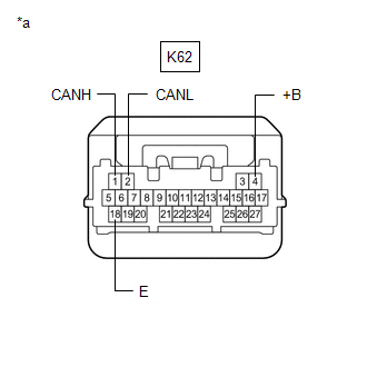
(b) Disconnect the K62 certification ECU (smart key ECU assembly) connector.
(c) Measure the resistance according to the value(s) in the table below.
Standard Resistance:
|
Terminal No. (Symbol) | Wiring Color |
Terminal Description | Condition |
Specified Condition |
|---|---|---|---|---|
|
K62-1 (CANH) - K62-2 (CANL) |
G - W | HIGH-level CAN bus line - LOW-level CAN bus line |
Cable disconnected from negative (-) battery terminal |
54 to 69 Ω |
|
K62-1 (CANH) - K62-18 (E) |
G - W-B | HIGH-level CAN bus line - Ground |
Cable disconnected from negative (-) battery terminal |
200 Ω or higher |
|
K62-2 (CANL) - K62-18 (E) |
W - W-B | LOW-level CAN bus line - Ground |
Cable disconnected from negative (-) battery terminal |
200 Ω or higher |
|
K62-1 (CANH) - K62-4 (+B) |
G - W | HIGH-level CAN bus line - Battery positive (+) |
Cable disconnected from negative (-) battery terminal |
6 kΩ or higher |
|
K62-2 (CANL) - K62-4 (+B) |
W - W | LOW-level CAN bus line - Battery positive (+) |
Cable disconnected from negative (-) battery terminal |
6 kΩ or higher |
|
*a | Front view of wire harness connector (to Certification ECU (Smart Key ECU Assembly)) |
RACK AND PINION POWER STEERING GEAR ASSEMBLY
Refer to Terminals of ECU.
Click here
(a) Disconnect the cable from the negative (-) battery terminal.
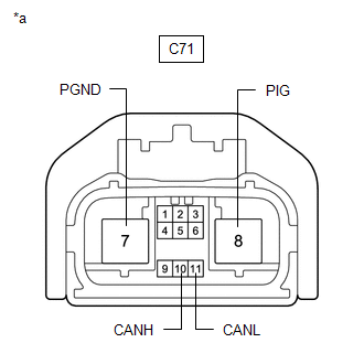
(b) Disconnect the C71 rack and pinion power steering gear assembly connector.
(c) Measure the resistance according to the value(s) in the table below.
|
*a | Front view of wire harness connector (to Rack and Pinion Power Steering Gear Assembly) |
Standard Resistance:
|
Terminal No. (Symbol) | Wiring Color |
Terminal Description | Condition |
Specified Condition |
|---|---|---|---|---|
|
C71-10 (CANH) - C71-11 (CANL) |
G - W | HIGH-level CAN bus line - LOW-level CAN bus line |
Cable disconnected from negative (-) battery terminal |
54 to 69 Ω |
|
C71-10 (CANH) - C71-7 (PGND) |
G - B | HIGH-level CAN bus line - Ground |
Cable disconnected from negative (-) battery terminal |
200 Ω or higher |
|
C71-11 (CANL) - C71-7 (PGND) |
W - B | LOW-level CAN bus line - Ground |
Cable disconnected from negative (-) battery terminal |
200 Ω or higher |
|
C71-10 (CANH) - C71-8 (PIG) |
G - W | HIGH-level CAN bus line - Battery positive (+) |
Cable disconnected from negative (-) battery terminal |
6 kΩ or higher |
|
C71-11 (CANL) - C71-8 (PIG) |
W - W | LOW-level CAN bus line - Battery positive (+) |
Cable disconnected from negative (-) battery terminal |
6 kΩ or higher |
AIRBAG SENSOR ASSEMBLY
Refer to Terminals of ECU.
Click here
(a) Disconnect the cable from the negative (-) battery terminal.
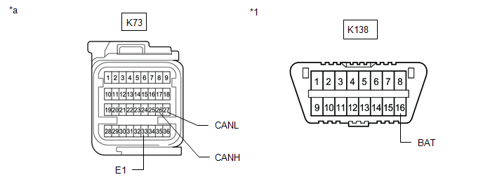
(b) Disconnect the K73 airbag sensor assembly connector.
(c) Measure the resistance according to the value(s) in the table below.
|
*1 | DLC3 |
- | - |
|
*a | Front view of wire harness connector (to Airbag Sensor Assembly) |
- | - |
Standard Resistance:
|
Terminal No. (Symbol) | Wiring Color |
Terminal Description | Condition |
Specified Condition |
|---|---|---|---|---|
|
K73-26 (CANH) - K73-27 (CANL) |
R - W | HIGH-level CAN bus line - LOW-level CAN bus line |
Cable disconnected from negative (-) battery terminal |
108 to 132 Ω |
|
K73-26 (CANH) - K73-33 (E1) |
R - W-B | HIGH-level CAN bus line - Ground |
Cable disconnected from negative (-) battery terminal |
200 Ω or higher |
|
K73-27 (CANL) - K73-33 (E1) |
W - W-B | LOW-level CAN bus line - Ground |
Cable disconnected from negative (-) battery terminal |
200 Ω or higher |
|
K73-26 (CANH) - K138-16 (BAT) |
R - R | HIGH-level CAN bus line - Battery positive (+) |
Cable disconnected from negative (-) battery terminal |
6 kΩ or higher |
|
K73-27 (CANL) - K138-16 (BAT) |
W - R | LOW-level CAN bus line - Battery positive (+) |
Cable disconnected from negative (-) battery terminal |
6 kΩ or higher |
AIR CONDITIONING AMPLIFIER ASSEMBLY
Refer to Terminals of ECU.
- for Automatic Air Conditioning System
Click here
- for Manual Air Conditioning System
Click here
(a) Disconnect the cable from the negative (-) battery terminal.
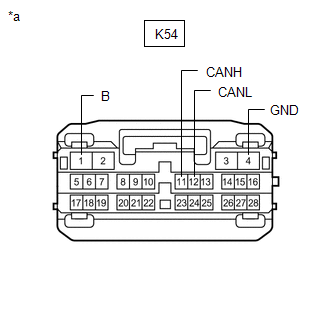
(b) Disconnect the K54 air conditioning amplifier assembly connector.
(c) Measure the resistance according to the value(s) in the table below.
Standard Resistance:
|
Terminal No. (Symbol) | Wiring Color |
Terminal Description | Condition |
Specified Condition |
|---|---|---|---|---|
|
K54-11 (CANH) - K54-12 (CANL) |
SB - W | HIGH-level CAN bus line - LOW-level CAN bus line |
Cable disconnected from negative (-) battery terminal |
54 to 69 Ω |
|
K54-11 (CANH) - K54-4 (GND) |
SB - W-B | HIGH-level CAN bus line - Ground |
Cable disconnected from negative (-) battery terminal |
200 Ω or higher |
|
K54-12 (CANL) - K54-4 (GND) |
W - W-B | LOW-level CAN bus line - Ground |
Cable disconnected from negative (-) battery terminal |
200 Ω or higher |
|
K54-11 (CANH) - K54-1 (B) |
SB - LA-B | HIGH-level CAN bus line - Battery positive (+) |
Cable disconnected from negative (-) battery terminal |
6 kΩ or higher |
|
K54-12 (CANL) - K54-1 (B) |
W - LA-B | LOW-level CAN bus line - Battery positive (+) |
Cable disconnected from negative (-) battery terminal |
6 kΩ or higher |
|
*a | Front view of wire harness connector (to Air Conditioning Amplifier Assembly) |
RADIO AND DISPLAY RECEIVER ASSEMBLY
Refer to Terminals of ECU.
- for Audio and Visual System
Click here
- for Navigation System
Click here
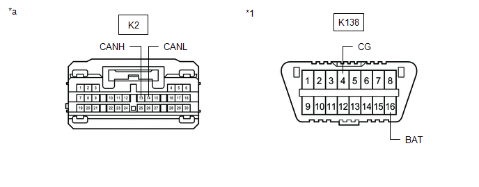
(a) Disconnect the cable from the negative (-) battery terminal.
(b) Disconnect the K2 radio and display receiver assembly connector.
(c) Measure the resistance according to the value(s) in the table below.
|
*1 | DLC3 |
- | - |
|
*a | Front view of wire harness connector (to Radio and Display Receiver Assembly) |
- | - |
Standard Resistance:
|
Terminal No. (Symbol) | Wiring Color |
Terminal Description | Condition |
Specified Condition |
|---|---|---|---|---|
|
K2-13 (CANH) - K2-14 (CANL) |
B - W | HIGH-level CAN bus line - LOW-level CAN bus line |
Cable disconnected from negative (-) battery terminal |
54 to 69 Ω |
|
K2-13 (CANH) - K138-4 (CG) |
B - W-B | HIGH-level CAN bus line - Ground |
Cable disconnected from negative (-) battery terminal |
200 Ω or higher |
|
K2-14 (CANL) - K138-4 (CG) |
W - W-B | LOW-level CAN bus line - Ground |
Cable disconnected from negative (-) battery terminal |
200 Ω or higher |
|
K2-13 (CANH) - K138-16 (BAT) |
B - R | HIGH-level CAN bus line - Battery positive (+) |
Cable disconnected from negative (-) battery terminal |
6 kΩ or higher |
|
K2-14 (CANL) - K138-16 (BAT) |
W - R | LOW-level CAN bus line - Battery positive (+) |
Cable disconnected from negative (-) battery terminal |
6 kΩ or higher |
BLIND SPOT MONITOR SENSOR RH (w/ Blind Spot Monitor System)
Refer to Terminals of ECU.
Click here
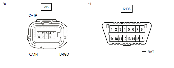
(a) Disconnect the cable from the negative (-) battery terminal.
(b) Disconnect the W5 blind spot monitor sensor RH connector.
(c) Measure the resistance according to the value(s) in the table below.
|
*1 | DLC3 |
- | - |
|
*a | Front view of wire harness connector (to Blind Spot Monitor Sensor RH) |
- | - |
Standard Resistance:
|
Terminal No. (Symbol) | Wiring Color |
Terminal Description | Condition |
Specified Condition |
|---|---|---|---|---|
|
W5-2 (CA1P) - W5-7 (CA1N) |
V - W | HIGH-level CAN bus line - LOW-level CAN bus line |
Cable disconnected from negative (-) battery terminal |
54 to 69 Ω |
|
W5-2 (CA1P) - W5-10 (BRGD) |
V - W-B | HIGH-level CAN bus line - Ground |
Cable disconnected from negative (-) battery terminal |
200 Ω or higher |
|
W5-7 (CA1N) - W5-10 (BRGD) |
W - W-B | LOW-level CAN bus line - Ground |
Cable disconnected from negative (-) battery terminal |
200 Ω or higher |
|
W5-2 (CA1P) - K138-16 (BAT) |
V - R | HIGH-level CAN bus line - Battery positive (+) |
Cable disconnected from negative (-) battery terminal |
6 kΩ or higher |
|
W5-7 (CA1N) - K138-16 (BAT) |
W - R | LOW-level CAN bus line - Battery positive (+) |
Cable disconnected from negative (-) battery terminal |
6 kΩ or higher |
FORWARD RECOGNITION CAMERA (w/ Front Camera System)
Refer to Terminals of ECU.
Click here
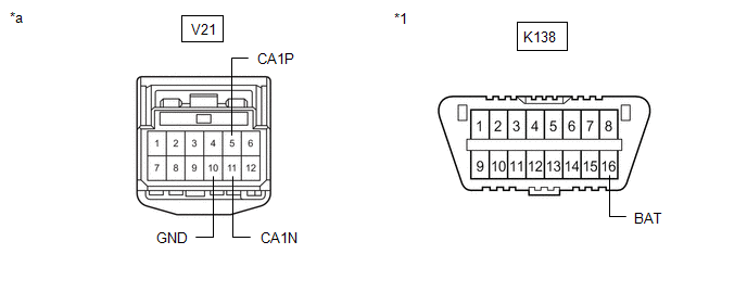
(a) Disconnect the cable from the negative (-) battery terminal.
(b) Disconnect the V21 forward recognition camera connector.
(c) Measure the resistance according to the value(s) in the table below.
|
*1 | DLC3 |
- | - |
|
*a | Front view of wire harness connector (to Forward Recognition Camera) |
- | - |
Standard Resistance:
|
Terminal No. (Symbol) | Wiring Color |
Terminal Description | Condition |
Specified Condition |
|---|---|---|---|---|
|
V21-5 (CA1P) - V21-11 (CA1N) |
L - W | HIGH-level CAN bus line - LOW-level CAN bus line |
Cable disconnected from negative (-) battery terminal |
54 to 69 Ω |
|
V21-5 (CA1P) - V21-10 (GND) |
L - W-B | HIGH-level CAN bus line - Ground |
Cable disconnected from negative (-) battery terminal |
200 Ω or higher |
|
V21-11 (CA1N) - V21-10 (GND) |
W - W-B | LOW-level CAN bus line - Ground |
Cable disconnected from negative (-) battery terminal |
200 Ω or higher |
|
V21-5 (CA1P) - K138-16 (BAT) |
L - R | HIGH-level CAN bus line - Battery positive (+) |
Cable disconnected from negative (-) battery terminal |
6 kΩ or higher |
|
V21-11 (CA1N) - K138-16 (BAT) |
W - R | LOW-level CAN bus line - Battery positive (+) |
Cable disconnected from negative (-) battery terminal |
6 kΩ or higher |
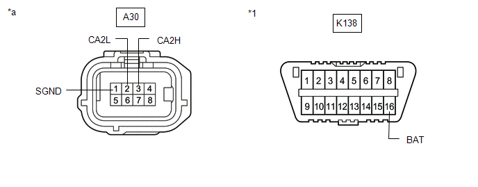
MILLIMETER WAVE RADAR SENSOR ASSEMBLY (w/ Front Camera System)
Refer to Terminals of ECU.
Click here
(a) Disconnect the cable from the negative (-) battery terminal.
(b) Disconnect the A30 millimeter wave radar sensor assembly connector.
(c) Measure the resistance according to the value(s) in the table below.
|
*1 | DLC3 |
- | - |
|
*a | Front view of wire harness connector (to Millimeter Wave Radar Sensor Assembly) |
- | - |
Standard Resistance:
|
Terminal No. (Symbol) | Wiring Color |
Terminal Description | Condition |
Specified Condition |
|---|---|---|---|---|
|
A30-3 (CA2H) - A30-2 (CA2L) |
R - W | HIGH-level CAN bus line - LOW-level CAN bus line |
Cable disconnected from negative (-) battery terminal |
54 to 69 Ω |
|
A30-3 (CA2H) - A30-1 (SGND) |
R - W-B | HIGH-level CAN bus line - Ground |
Cable disconnected from negative (-) battery terminal |
200 Ω or higher |
|
A30-2 (CA2L) - A30-1 (SGND) |
W - W-B | LOW-level CAN bus line - Ground |
Cable disconnected from negative (-) battery terminal |
200 Ω or higher |
|
A30-3 (CA2H) - K138-16 (BAT) |
R - R | HIGH-level CAN bus line - Battery positive (+) |
Cable disconnected from negative (-) battery terminal |
6 kΩ or higher |
|
A30-2 (CA2L) - K138-16 (BAT) |
W - R | LOW-level CAN bus line - Battery positive (+) |
Cable disconnected from negative (-) battery terminal |
6 kΩ or higher |
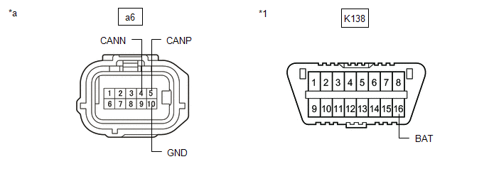
OCCUPANT DETECTION ECU
Refer to Terminals of ECU.
Click here
(a) Disconnect the cable from the negative (-) battery terminal.
(b) Disconnect the a6 occupant detection ECU connector.
(c) Measure the resistance according to the value(s) in the table below.
|
*1 | DLC3 |
- | - |
|
*a | Front view of wire harness connector (to Occupant Detection ECU) |
- | - |
Standard Resistance:
|
Terminal No. (Symbol) | Wiring Color |
Terminal Description | Condition |
Specified Condition |
|---|---|---|---|---|
|
a6-5 (CANP) - a6-4 (CANN) |
L - W | HIGH-level CAN bus line - LOW-level CAN bus line |
Cable disconnected from negative (-) battery terminal |
54 to 69 Ω |
|
a6-5 (CANP) - a6-10 (GND) |
L - W-B | HIGH-level CAN bus line - Ground |
Cable disconnected from negative (-) battery terminal |
200 Ω or higher |
|
a6-4 (CANN) - a6-10 (GND) |
W - W-B | LOW-level CAN bus line - Ground |
Cable disconnected from negative (-) battery terminal |
200 Ω or higher |
|
a6-5 (CANP) - K138-16 (BAT) |
L - R | HIGH-level CAN bus line - Battery positive (+) |
Cable disconnected from negative (-) battery terminal |
6 kΩ or higher |
|
a6-4 (CANN) - K138-16 (BAT) |
W - R | LOW-level CAN bus line - Battery positive (+) |
Cable disconnected from negative (-) battery terminal |
6 kΩ or higher |
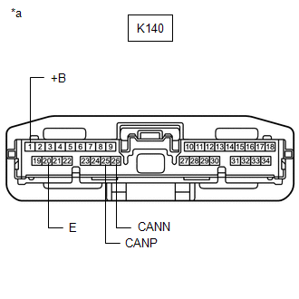
DCM (TELEMATICS TRANSCEIVER) (w/ Telematics Transceiver)
Refer to Terminals of ECU.
Click here
(a) Disconnect the cable from the negative (-) battery terminal.
(b) Disconnect the K140 DCM (telematics transceiver) connector.
(c) Measure the resistance according to the value(s) in the table below.
|
*a | Front view of wire harness connector (to DCM (Telematics Transceiver)) |
Standard Resistance:
|
Terminal No. (Symbol) | Wiring Color |
Terminal Description | Condition |
Specified Condition |
|---|---|---|---|---|
|
K140-25 (CANP) - K140-26 (CANN) |
R - W | HIGH-level CAN bus line - LOW-level CAN bus line |
Cable disconnected from negative (-) battery terminal |
54 to 69 Ω |
|
K140-25 (CANP) - K140-20 (E) |
R - W-B | HIGH-level CAN bus line - Ground |
Cable disconnected from negative (-) battery terminal |
200 Ω or higher |
|
K140-26 (CANN) - K140-20 (E) |
W - W-B | LOW-level CAN bus line - Ground |
Cable disconnected from negative (-) battery terminal |
200 Ω or higher |
|
K140-25 (CANP) - K140-1 (+B) |
R - B | HIGH-level CAN bus line - Battery positive (+) |
Cable disconnected from negative (-) battery terminal |
6 kΩ or higher |
|
K140-26 (CANN) - K140-1 (+B) |
W - B | LOW-level CAN bus line - Battery positive (+) |
Cable disconnected from negative (-) battery terminal |
6 kΩ or higher |
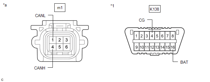
REAR TELEVISION CAMERA ASSEMBLY (w/ Parking Assist Monitor System or Panoramic View Monitor System)
Refer to Terminals of ECU.
- w/ Parking Assist Monitor System
Click here
- w/ Panoramic View Monitor System
Click here
(a) Disconnect the cable from the negative (-) battery terminal.
(b) Disconnect the m1 rear television camera assembly connector.
(c) Measure the resistance according to the value(s) in the table below.
|
*1 | DLC3 |
- | - |
|
*a | Front view of wire harness connector (to Rear Television Camera Assembly) |
- | - |
Standard Resistance:
|
Terminal No. (Symbol) | Wiring Color |
Terminal Description | Condition |
Specified Condition |
|---|---|---|---|---|
|
m1-4 (CANH) - m1-1 (CANL) |
R - W | HIGH-level CAN bus line - LOW-level CAN bus line |
Cable disconnected from negative (-) battery terminal |
54 to 69 Ω |
|
m1-4 (CANH) - K138-4 (CG) |
R - W-B | HIGH-level CAN bus line - Ground |
Cable disconnected from negative (-) battery terminal |
200 Ω or higher |
|
m1-1 (CANL) - K138-4 (CG) |
W - W-B | LOW-level CAN bus line - Ground |
Cable disconnected from negative (-) battery terminal |
200 Ω or higher |
|
m1-4 (CANH) - K138-16 (BAT) |
R - R | HIGH-level CAN bus line - Battery positive (+) |
Cable disconnected from negative (-) battery terminal |
6 kΩ or higher |
|
m1-1 (CANL) - K138-16 (BAT) |
W - R | LOW-level CAN bus line - Battery positive (+) |
Cable disconnected from negative (-) battery terminal |
6 kΩ or higher |
CLEARANCE WARNING ECU ASSEMBLY (w/ Intuitive Parking Assist System)
Refer to Terminals of ECU.
- w/ Intuitive Parking Assist System
Click here
- w/ Parking Support Brake System
Click here
(a) Disconnect the cable from the negative (-) battery terminal.
(b) Disconnect the R39 clearance warning ECU assembly connector.
(c) Measure the resistance according to the value(s) in the table below.
|
*1 | DLC3 |
- | - |
|
*a | Front view of wire harness connector (to Clearance Warning ECU Assembly) |
- | - |
Standard Resistance:
|
Terminal No. (Symbol) | Wiring Color |
Terminal Description | Condition |
Specified Condition |
|---|---|---|---|---|
|
R39-17 (R1) - R39-18 (R2) |
L - W | HIGH-level CAN bus line - LOW-level CAN bus line |
Cable disconnected from negative (-) battery terminal |
54 to 69 Ω |
|
R39-17 (R1) - R39-31 (E) |
L - W-B | HIGH-level CAN bus line - Ground |
Cable disconnected from negative (-) battery terminal |
200 Ω or higher |
|
R39-18 (R2) - R39-31 (E) |
W - W-B | LOW-level CAN bus line - Ground |
Cable disconnected from negative (-) battery terminal |
200 Ω or higher |
|
R39-17 (R1) - K138-16 (BAT) |
L - R | HIGH-level CAN bus line - Battery positive (+) |
Cable disconnected from negative (-) battery terminal |
6 kΩ or higher |
|
R39-18 (R2) - K138-16 (BAT) |
W - R | LOW-level CAN bus line - Battery positive (+) |
Cable disconnected from negative (-) battery terminal |
6 kΩ or higher |
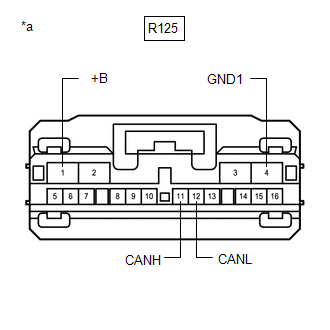
TELEVISION CAMERA CONTROLLER (w/ Panoramic View Monitor System)
Refer to Terminals of ECU.
Click here
(a) Disconnect the cable from the negative (-) battery terminal.
(b) Disconnect the R125 television camera controller connector.
(c) Measure the resistance according to the value(s) in the table below.
Standard Resistance:
|
Terminal No. (Symbol) | Wiring Color |
Terminal Description | Condition |
Specified Condition |
|---|---|---|---|---|
|
R125-11 (CANH) - R125-12 (CANL) |
GR - W | HIGH-level CAN bus line - LOW-level CAN bus line |
Cable disconnected from negative (-) battery terminal |
54 to 69 Ω |
|
R125-11 (CANH) - R125-4 (GND1) |
GR - W-B | HIGH-level CAN bus line - Ground |
Cable disconnected from negative (-) battery terminal |
200 Ω or higher |
|
R125-12 (CANL) - R125-4 (GND1) |
W - W-B | LOW-level CAN bus line - Ground |
Cable disconnected from negative (-) battery terminal |
200 Ω or higher |
|
R125-11 (CANH) - R125-1 (+B) |
GR - R | HIGH-level CAN bus line - Battery positive (+) |
Cable disconnected from negative (-) battery terminal |
6 kΩ or higher |
|
R125-12 (CANL) - R125-1 (+B) |
W - R | LOW-level CAN bus line - Battery positive (+) |
Cable disconnected from negative (-) battery terminal |
6 kΩ or higher |
|
*a | Front view of wire harness connector (to Television Camera Controller) |
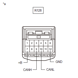
TIRE PRESSURE WARNING ECU AND RECEIVER (for Tire Pressure Warning System with Tire Inflation Pressure Display Function (w/o Smart Key System))
Refer to Terminals of ECU.
Click here
(a) Disconnect the cable from the negative (-) battery terminal.
(b) Disconnect the R128 tire pressure warning ECU and receiver connector.
(c) Measure the resistance according to the value(s) in the table below.
|
*a | Front view of wire harness connector (to Tire Pressure Warning ECU and Receiver) |
Standard Resistance:
|
Terminal No. (Symbol) | Wiring Color |
Terminal Description | Condition |
Specified Condition |
|---|---|---|---|---|
|
R128-9 (CANH) - R128-10 (CANL) |
L - W | HIGH-level CAN bus line - LOW-level CAN bus line |
Cable disconnected from negative (-) battery terminal |
54 to 69 Ω |
|
R128-9 (CANH) - R128-12 (GND) |
L - W-B | HIGH-level CAN bus line - Ground |
Cable disconnected from negative (-) battery terminal |
200 Ω or higher |
|
R128-10 (CANL) - R128-12 (GND) |
W - W-B | LOW-level CAN bus line - Ground |
Cable disconnected from negative (-) battery terminal |
200 Ω or higher |
|
R128-9 (CANH) - R128-7 (+B) |
L - LA-L | HIGH-level CAN bus line - Battery positive (+) |
Cable disconnected from negative (-) battery terminal |
6 kΩ or higher |
|
R128-10 (CANL) - R128-7 (+B) |
W - LA-L | LOW-level CAN bus line - Battery positive (+) |
Cable disconnected from negative (-) battery terminal |
6 kΩ or higher |
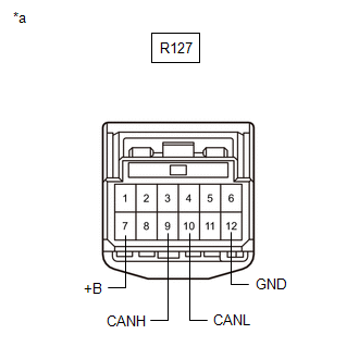
TIRE PRESSURE WARNING ECU AND RECEIVER (for Tire Pressure Warning System with Tire Inflation Pressure Display Function (w/ Smart Key System))
Refer to Terminals of ECU.
Click here
(a) Disconnect the cable from the negative (-) battery terminal.
(b) Disconnect the R127 tire pressure warning ECU and receiver connector.
(c) Measure the resistance according to the value(s) in the table below.
|
*a | Front view of wire harness connector (to Tire Pressure Warning ECU and Receiver) |
Standard Resistance:
|
Terminal No. (Symbol) | Wiring Color |
Terminal Description | Condition |
Specified Condition |
|---|---|---|---|---|
|
R127-9 (CANH) - R127-10 (CANL) |
L - W | HIGH-level CAN bus line - LOW-level CAN bus line |
Cable disconnected from negative (-) battery terminal |
54 to 69 Ω |
|
R127-9 (CANH) - R127-12 (GND) |
L - W-B | HIGH-level CAN bus line - Ground |
Cable disconnected from negative (-) battery terminal |
200 Ω or higher |
|
R127-10 (CANL) - R127-12 (GND) |
W - W-B | LOW-level CAN bus line - Ground |
Cable disconnected from negative (-) battery terminal |
200 Ω or higher |
|
R127-9 (CANH) - R127-7 (+B) |
L - LA-R | HIGH-level CAN bus line - Battery positive (+) |
Cable disconnected from negative (-) battery terminal |
6 kΩ or higher |
|
R127-10 (CANL) - R127-7 (+B) |
W - LA-R | LOW-level CAN bus line - Battery positive (+) |
Cable disconnected from negative (-) battery terminal |
6 kΩ or higher |
4WD ECU ASSEMBLY (for AWD)
Refer to Terminals of ECU.
Click here
(a) Disconnect the cable from the negative (-) battery terminal.
(b) Disconnect the K145 4WD ECU assembly connector.
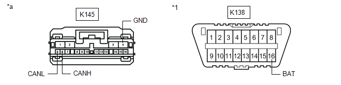
|
*1 | DLC3 |
- | - |
|
*a | Front view of wire harness connector (to 4WD ECU Assembly) |
- | - |
(c) Measure the resistance according to the value(s) in the table below.
Standard Resistance:
|
Terminal No. (Symbol) | Wiring Color |
Terminal Description | Condition |
Specified Condition |
|---|---|---|---|---|
|
K145-6 (CANH) - K145-5 (CANL) |
P - W | HIGH-level CAN bus line - LOW-level CAN bus line |
Cable disconnected from negative (-) battery terminal |
54 to 69 Ω |
|
K145-6 (CANH) - K145-4 (GND) |
P - W-B | HIGH-level CAN bus line - Ground |
Cable disconnected from negative (-) battery terminal |
200 Ω or higher |
|
K145-5 (CANL) - K145-4 (GND) |
W - W-B | LOW-level CAN bus line - Ground |
Cable disconnected from negative (-) battery terminal |
200 Ω or higher |
|
K145-6 (CANH) - K138-16 (BAT) |
P - R | HIGH-level CAN bus line - Battery positive (+) |
Cable disconnected from negative (-) battery terminal |
6 kΩ or higher |
|
K145-5 (CANL) - K138-16 (BAT) |
W - R | LOW-level CAN bus line - Battery positive (+) |
Cable disconnected from negative (-) battery terminal |
6 kΩ or higher |
READ NEXT:
 Diagnosis System
DIAGNOSIS SYSTEM CHECK FOR INSTALLED SYSTEMS (ECUS AND SENSORS) THAT USE CAN COMMUNICATION
(a) The systems (ECUs and sensors) that use CAN communication vary depending on the vehicle and optional eq
Dtc Combination Table
DTC COMBINATION TABLE HOW TO INTERPRET COMMUNICATION DTCS (DTCS THAT START WITH U)
(a) If a CAN communication error cannot be reproduced, determine the suspected malfunctioning part using the DTCs s
Dtc Check / Clear
DTC CHECK / CLEAR CHECK FOR DTC (a) Connect the Techstream to the DLC3.
(b) Turn the ignition switch to ON. (c) Turn the Techstream on.
(d) Enter the following menus: Body Electrical / Central Gat
SEE MORE:
Operation Check
OPERATION CHECK TOYOTA ENTUNE APP SUITE CONNECT RESET PROCEDURE
(a) Duplicate the problem symptom. (b) Check for DTCs and repair the systems for which any DTCs are output.
Click here
(c) Check cellular phone compatibility.
(1) Check if the cellular phone/vehicle is compatible (Refer to ht
Fuel Pump Control Circuit
DESCRIPTION The fuel pump (for low pressure side) circuit consists of the ECM, fuel pump (for low pressure side) and fuel pump control ECU (which operates the fuel pump (for low pressure side)). Based on the engine output, the ECM determines the fuel pump speed. The speed is then converted to a duty
