Toyota Camry (XV70): Terminals Of Ecu
TERMINALS OF ECU
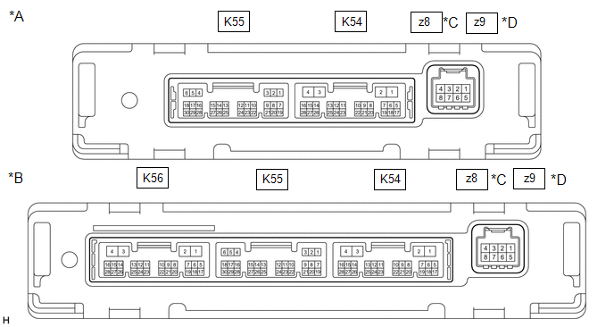
CHECK AIR CONDITIONING AMPLIFIER ASSEMBLY
|
*A | w/o Seat Heater System |
*B | w/ Seat Heater System |
|
*C | Dual Type Automatic Air Conditioning System |
*D | Single Type Automatic Air Conditioning System |
(a) Disconnect the K54 air conditioning amplifier assembly connector.
(b) Measure the voltage and resistance according to the value(s) in the table below.
HINT:
Measure the values on the wire harness side with the connector disconnected.
|
Terminal No. (Symbol) |
Terminal Description |
Condition | Specified Condition |
|---|---|---|---|
|
K54-2 (IG+) - K54-4 (GND) |
Power source (IG) |
Ignition switch ON |
11 to 14 V |
|
K54-2 (IG+) - K54-4 (GND) |
Power source (IG) |
Ignition switch off |
Below 1 V |
|
K54-4 (GND) - Body ground |
Ground | Always |
Below 1 Ω |
(c) Reconnect the K54 air conditioning amplifier assembly connector.
(d) Measure the voltage and check for pulses according to the value(s) in the table below.
|
Terminal No. (Symbol) |
Terminal Description |
Condition | Specified Condition |
|---|---|---|---|
|
K54-5 (RDFG) - K54-4 (GND) |
Rear window defogger signal |
Ignition switch ON, rear window defogger switch off |
11 to 14 V |
|
K54-5 (RDFG) - K54-4 (GND) |
Rear window defogger signal |
Ignition switch ON, rear window defogger switch on |
Below 1 V |
|
K54-14 (LIN1) - K54-4 (GND) |
LIN communication line |
Ignition switch ON |
Pulse generation |
CHECK AIR CONDITIONING CONTROL ASSEMBLY

(a) Disconnect the K26 air conditioning control assembly connector.
(b) Measure the voltage and resistance according to the value(s) in the table below.
HINT:
Measure the values on the wire harness side with the connector disconnected.
|
Terminal No. (Symbol) |
Terminal Description |
Condition | Specified Condition |
|---|---|---|---|
|
K26-2 (IG+) - K26-6 (GND) |
Power source (IG) |
Ignition switch ON |
11 to 14 V |
|
K26-2 (IG+) - K26-6 (GND) |
Power source (IG) |
Ignition switch off |
Below 1 V |
|
K26-6 (GND) - Body ground |
Ground | Always |
Below 1 Ω |
(c) Reconnect the K26 air conditioning control assembly connector.
(d) Check for pulses according to the value(s) in the table below.
|
Terminal No. (Symbol) |
Terminal Description |
Condition | Specified Condition |
|---|---|---|---|
|
K26-9 (LIN1) - K26-6 (GND) |
LIN communication line |
Ignition switch ON |
Pulse generation |
READ NEXT:
 Diagnosis System
DIAGNOSIS SYSTEM CHECK DLC3 (a) Check the DLC3.
Click here INSPECT BATTERY VOLTAGE
(a) Measure the battery voltage. Standard Voltage: 11 to 14 V
If the voltage is below 11 V, recharge or r
Data List / Active Test
DATA LIST / ACTIVE TEST ACTIVE TEST HINT:
Using the Techstream to perform Active Tests allows relays, VSVs, actuators and other items to be operated without removing any parts. This non-intrusive f
Rear Window Defogger System does not Operate
DESCRIPTION When the rear window defogger switch on the air conditioning control assembly is pressed, the operation signal is transmitted to the air conditioning amplifier assembly via LIN communicati
SEE MORE:
Components
COMPONENTS ILLUSTRATION
*1 AUTO HIGH BEAM SWITCH
*2 COWL SIDE TRIM SUB-ASSEMBLY LH
*3 FRONT DOOR OPENING TRIM WEATHERSTRIP LH
*4 FRONT DOOR SCUFF PLATE LH
*5 HOOD LOCK CONTROL LEVER SUB-ASSEMBLY
*6 INSTRUMENT SIDE PANEL LH
*7
Components
COMPONENTS ILLUSTRATION
*1 AIR CLEANER ASSEMBLY WITH AIR CLEANER HOSE
*2 COOL AIR INTAKE DUCT SEAL
*3 ECM
*4 INLET AIR CLEANER ASSEMBLY
*5 NO. 1 ECM BRACKET
*6 NO. 2 ECM BRACKET
*7 VACUUM HOSE
*8 NO. 1 FUEL VAPOR FEED HOSE
