
Toyota Camry (XV70): Components
COMPONENTS
ILLUSTRATION
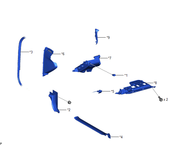
|
*1 | AUTO HIGH BEAM SWITCH |
*2 | COWL SIDE TRIM SUB-ASSEMBLY LH |
|
*3 | FRONT DOOR OPENING TRIM WEATHERSTRIP LH |
*4 | FRONT DOOR SCUFF PLATE LH |
|
*5 | HOOD LOCK CONTROL LEVER SUB-ASSEMBLY |
*6 | INSTRUMENT SIDE PANEL LH |
|
*7 | NO. 1 INSTRUMENT PANEL SUB-ASSEMBLY |
*8 | NO. 1 INSTRUMENT PANEL UNDER COVER SUB-ASSEMBLY |
|
*9 | NO. 2 METER HOOD CLUSTER |
- | - |
READ NEXT:
 Removal
REMOVAL PROCEDURE 1. REMOVE FRONT DOOR SCUFF PLATE LH
Click here
2. REMOVE COWL SIDE TRIM SUB-ASSEMBLY LH
Click here
3. REMOVE NO. 1 INSTRUMEN
Inspection
INSPECTION PROCEDURE 1. INSPECT AUTO HIGH BEAM SWITCH
*a Component without harness connected
(Auto High Beam Switch) (a) Measure the resistance according to the value(s) in the
Installation
INSTALLATION PROCEDURE 1. INSTALL AUTO HIGH BEAM SWITCH
(a) Engage the 2 claws to install the auto high beam switch as shown in the illustration.
Install in this Direction 2
SEE MORE:
Air Conditioner ECU Vehicle Information Reading/Writing Processor Malfunction (B15F5)
DESCRIPTION This DTC may be stored when items controlled by the air conditioning amplifier assembly cannot be customized via the navigation system vehicle customization screen.
HINT: The air conditioning amplifier assembly controls the air conditioning system related items that are customizable vi
Problem Symptoms Table
PROBLEM SYMPTOMS TABLE
HINT:
Use the table below to help determine the cause of problem symptoms. If multiple suspected areas are listed, the potential causes of the symptoms are listed in order of probability in the "Suspected Area" column of the table. Check each symptom by checking the susp
© 2023-2026 Copyright www.tocamry.com
