
Toyota Camry (XV70): Installation
INSTALLATION
PROCEDURE
1. INSTALL AUTO HIGH BEAM SWITCH
(a) Engage the 2 claws to install the auto high beam switch as shown in the illustration.
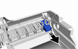
.png) |
Install in this Direction |
2. INSTALL NO. 1 INSTRUMENT PANEL SUB-ASSEMBLY
Click here .gif)
3. CONNECT HOOD LOCK CONTROL LEVER SUB-ASSEMBLY
Click here
4. INSTALL NO. 2 METER HOOD CLUSTER
Click here
5. INSTALL INSTRUMENT SIDE PANEL LH
Click here
6. INSTALL FRONT DOOR OPENING TRIM WEATHERSTRIP LH
Click here
7. INSTALL NO. 1 INSTRUMENT PANEL UNDER COVER SUB-ASSEMBLY
Click here
8. INSTALL COWL SIDE TRIM SUB-ASSEMBLY LH
Click here
9. INSTALL FRONT DOOR SCUFF PLATE LH
Click here
READ NEXT:
 Components
COMPONENTS ILLUSTRATION
*1 AUTOMATIC LIGHT CONTROL SENSOR
*2 DEFROSTER NOZZLE ASSEMBLY
*3 NO. 1 SIDE DEFROSTER NOZZLE DUCT
*4 NO. 2 SIDE DEFROSTER NOZZLE DU
On-vehicle Inspection
ON-VEHICLE INSPECTION PROCEDURE
1. INSPECT AUTOMATIC LIGHT CONTROL SENSOR
*a Front view of wire harness connector
(to Automatic Light Control Sensor)
(a) Disconnect the M1
SEE MORE:
Terminals Of Ecu
TERMINALS OF ECU CHECK MAIN BODY ECU (MULTIPLEX NETWORK BODY ECU) AND INSTRUMENT PANEL JUNCTION BLOCK ASSEMBLY
(a) Remove the main body ECU (multiplex network body ECU) from the instrument panel junction block assembly.
Click here (b) Reconnect the instrument panel junction block assembly conne
If the electronic key does
not operate properly (vehicles with a smart key system)
If communication between the electronic key and vehicle is
interrupted or the electronic key cannot be used
because the battery is depleted, the smart key system and wireless
remote control cannot be used. In such cases, the doors
and trunk can be opened and the engine can be started by followin
© 2023-2026 Copyright www.tocamry.com
