Toyota Camry (XV70): Terminals Of Ecu
TERMINALS OF ECU
CHECK MAIN BODY ECU (MULTIPLEX NETWORK BODY ECU) AND INSTRUMENT PANEL JUNCTION BLOCK ASSEMBLY
(a) Remove the main body ECU (multiplex network body ECU) from the instrument panel junction block assembly.
Click here .gif)
(b) Reconnect the instrument panel junction block assembly connectors.
(c) Measure the resistance and voltage according to the value(s) in the table below.
HINT:
Measure the values on the wire harness side with the connector disconnected.
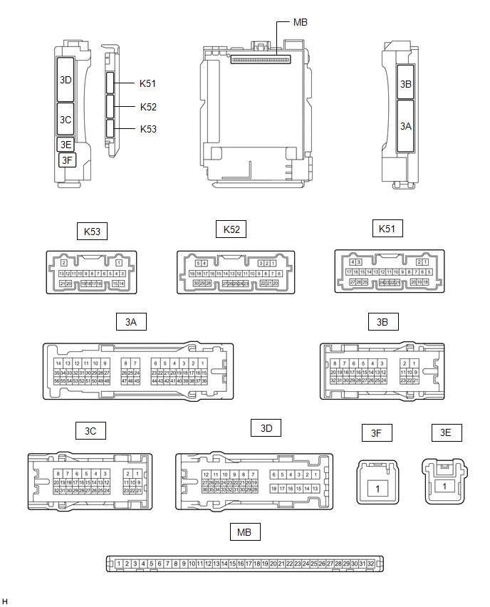
|
Terminal No. (Symbol) | Wiring Color |
Input/Output | Terminal Description |
Condition | Specified Condition |
Related Data List Item |
|---|---|---|---|---|---|---|
|
MB-11 (GND1) - Body ground |
- | - |
Ground | Always |
Below 1 ? | - |
|
MB-30 (ACC) - Body ground |
- | Input |
ACC power supply | Ignition switch ACC |
11 to 14 V |
ACC SW |
| Ignition switch off |
Below 1 V | |||||
|
MB-31 (BECU) - Body ground |
- | Input |
Battery power supply |
Always | 11 to 14 V |
- |
|
MB-32 (IG) - Body ground |
- | Input |
IG power supply | Ignition switch ON |
11 to 14 V |
IG SW |
| Ignition switch off |
Below 1 V |
(d) Install the main body ECU (multiplex network body ECU) to instrument panel junction block assembly.
Click here
(e) Measure the voltage and check for pulses according to the value(s) in the table below.
|
Terminal No. (Symbol) | Wiring Color |
Input/Output | Terminal Description |
Condition | Specified Condition |
Related Data List Item |
|---|---|---|---|---|---|---|
|
K52-1 (FLCY) - Body ground |
W- Body ground | Input |
Front door courtesy light switch (for LH) input |
Front door LH open > closed |
Below 1 V > 11 to 14 V or pulse output (maximum 14 V)* |
FL Door Courtesy SW |
|
3A-41 (KSW) - Body ground |
V - Body ground | Input |
Key unlock warning switch input |
No key in ignition key cylinder > Key in ignition key cylinder |
11 to 14 V > Below 1 V |
Key Unlock Warning SW |
- *: Differs depending on the vehicle model
READ NEXT:
SEE MORE:
 Display does not Dim when Light Control Switch is Turned ON
CAUTION / NOTICE / HINT
NOTICE:
Depending on the parts that are replaced during vehicle inspection or maintenance, performing initialization, registration or calibration may be needed. Refer to Precaution for Audio and Visual System.
Click here
When replacing the radio and display
Removal
REMOVAL CAUTION / NOTICE / HINT
The necessary procedures (adjustment, calibration, initialization, or registration) that must be performed after parts are removed and installed, or replaced during automatic light control sensor removal/installation are shown below. Necessary Procedures After Part
