
Toyota Camry (XV70): Removal
REMOVAL
PROCEDURE
1. REMOVE FRONT DOOR SCUFF PLATE LH
Click here .gif)
2. REMOVE COWL SIDE TRIM SUB-ASSEMBLY LH
Click here
3. REMOVE NO. 1 INSTRUMENT PANEL UNDER COVER SUB-ASSEMBLY
Click here
4. DISCONNECT FRONT DOOR OPENING TRIM WEATHERSTRIP LH
Click here
5. REMOVE INSTRUMENT SIDE PANEL LH
Click here
6. REMOVE NO. 2 METER HOOD CLUSTER
Click here
7. DISCONNECT HOOD LOCK CONTROL LEVER SUB-ASSEMBLY
Click here
8. REMOVE NO. 1 INSTRUMENT PANEL SUB-ASSEMBLY
Click here
9. REMOVE AUTO HIGH BEAM SWITCH
(a) Using a screwdriver with its tip wrapped with protective tape, disengage the 2 claws and remove the auto high beam switch as shown in the illustration.
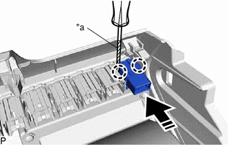
|
*a | Protective Tape |
.png) |
Remove in this Direction |
READ NEXT:
 Inspection
INSPECTION PROCEDURE 1. INSPECT AUTO HIGH BEAM SWITCH
*a Component without harness connected
(Auto High Beam Switch) (a) Measure the resistance according to the value(s) in the
Installation
INSTALLATION PROCEDURE 1. INSTALL AUTO HIGH BEAM SWITCH
(a) Engage the 2 claws to install the auto high beam switch as shown in the illustration.
Install in this Direction 2
SEE MORE:
Right Front Wheel Speed Sensor Internal Electronic Failure (C050649)
DESCRIPTION When the system is starting up and the skid control ECU (brake actuator assembly) detects a speed sensor circuit malfunction via the speed sensor circuit self-diagnosis function, this DTC is stored.
DTC No. Detection Item
DTC Detection Condition Trouble Area
C05064
Data List / Active Test
DATA LIST / ACTIVE TEST DATA LIST NOTICE:
In the table below, the values listed under "Normal Condition" are reference values. Do not depend solely on these reference values when deciding whether a part is faulty or not.
HINT: Using the Techstream to read the Data List allows the values or state
