
Toyota Camry (XV70): Terminals Of Ecu
TERMINALS OF ECU
CHECK AIR CONDITIONING AMPLIFIER ASSEMBLY
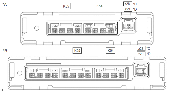
|
*A | w/o Seat Heater |
*B | w/ Seat Heater |
|
*C | for Dual Type |
*D | for Single Type |
HINT:
- Check from the rear of the connector while it is connected to the air conditioning amplifier assembly.
- Make sure to wait at least 2 minutes after turning the ignition switch off before performing an ECU terminal inspection.
|
Terminal No. (Symbol) |
Wiring Color | Terminal Description |
Condition | Specified Condition |
|---|---|---|---|---|
|
K55-1 (SG-1) - Body ground |
LG - Body ground | Ground for cooler (room temp. sensor) thermistor |
Always | Below 1 V |
|
K55-2 (SG-2) - Body ground |
W - Body ground | Ground for thermistor assembly |
Always | Below 1 V |
|
K55-3 (SG-4) - Body ground |
L - Body ground | Ground for air conditioner pressure sensor |
Always | Below 1 V |
|
K55-6 (S5-3) - K55-3 (SG-4) |
GR - L | Power supply for air conditioner pressure sensor |
Ignition switch ON | 4.75 to 5.25 V |
|
Ignition switch off | Below 1 V | |||
|
K55-9 (MGC) - K54-4 (GND)*3 |
G - W-B | Magnetic clutch operation signal |
| 11 to 14 V |
| Below 1 V | |||
|
K55-13 (TAM) - K55-2 (SG-2) |
R - W | Thermistor assembly signal |
| 1.05 to 1.45 V |
| 0.64 to 0.87 V | |||
|
K55-14 (TR) - K55-1 (SG-1) |
GR - LG | Cooler (room temp. sensor) thermistor signal |
| 1.05 to 1.45 V |
| 0.64 to 0.87 V | |||
|
K55-20 (ECOS) - K54-4 (GND)*4 |
W - W-B | ECO switch assembly (electric parking brake switch assembly) signal |
| 11 to 14 V |
| Below 1 V | |||
|
K55-21 (LOCK) - K55-2 (SG-2)*3 |
B - W | A/C lock sensor signal |
| Pulse generation (See waveform 1) |
|
K55-24 (PRE) - K55-3 (SG-4) |
W - L | Air conditioner pressure sensor signal |
| 4.61 V or higher |
| Below 0.74 V | |||
| 0.74 to 4.61 V | |||
|
K54-1 (B) - K54-4 (GND) |
LA-B - W-B | Power source (Back-up) |
Always | 11 to 14 V |
|
K54-2 (IG+) - K54-4 (GND) |
LA-GR - W-B | Power source (IG) |
Ignition switch ON | 11 to 14 V |
|
Ignition switch off | Below 1 V | |||
|
K54-3 (SOL+) - K54-4 (GND) |
R - W-B | Compressor solenoid operation signal |
| Pulse generation (See waveform 2) |
|
K54-4 (GND) - Body ground |
W-B - Body ground | Ground for main power supply |
Always | Below 1 V |
|
K54-6 (BLW) - K54-4 (GND) |
LG - W-B | Blower motor speed control signal |
| Pulse generation (See waveform 3) |
|
K54-11 (CANH) - K54-12 (CANL) |
SB - W | CAN communication system |
CAN communication is performed |
Pulse generation |
|
K54-14 (LIN1) - K54-4 (GND) |
W - W-B | LIN communication signal |
Ignition switch ON | Pulse generation (See waveform 4) |
|
z28-2 (BUS G) - Body ground*1 |
- | Ground for BUS IC |
Always | Below 1 V |
|
z28-3 (BUS) - z28-2 (BUS G)*1 |
- | BUS IC control signal |
Ignition switch ON | Pulse generation (See waveform 5) |
|
z28-4 (B BUS) - z28-2 (BUS G)*1 |
- | Power supply for BUS IC |
Ignition switch off | 11 to 14 V |
|
z28-5 (SG) - Body ground*1 |
GR - Body ground | Ground for No. 1 cooler thermistor |
Always | Below 1 V |
|
z28-6 (TE) - z28-5 (SG)*1 |
GR - GR | No. 1 cooler thermistor signal |
| 1.7 to 2.1 V |
| 0.9 to 1.3 V | |||
|
z29-2 (1A) - Body ground*2 |
- | Ground for BUS IC |
Always | Below 1 V |
|
z29-3 (2A) - z29-2 (1A)*2 |
- | BUS IC control signal |
Ignition switch ON | Pulse generation (See waveform 5) |
|
z29-4 (3A) - z29-2 (1A)*2 |
- | Power supply for BUS IC |
Ignition switch off | 11 to 14 V |
|
z29-5 (4A) - Body ground*2 |
GR - Body ground | Ground for No. 1 cooler thermistor |
Always | Below 1 V |
|
z29-6 (5A) - z29-5 (4A)*2 |
GR - GR | No. 1 cooler thermistor signal |
| 1.7 to 2.1 V |
| 0.9 to 1.3 V |
- *1: for Dual Type
- *2: for Single Type
- *3: for 2GR-FKS
- *4: w/ Electric Parking Brake System
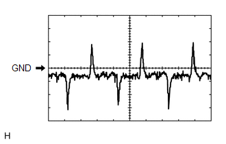
(a) Waveform 1:
|
Item | Content |
|---|---|
|
Terminal No. | K55-21 (LOCK) - K55-2 (SG-2) |
|
Tool Setting | 200 mV/DIV., 10 ms./DIV. |
|
Condition |
|
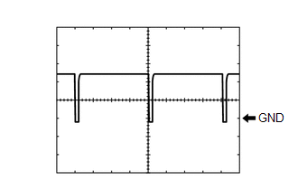
(b) Waveform 2:
|
Item | Content |
|---|---|
|
Terminal No. | K54-3 (SOL+) - K54-4 (GND) |
|
Tool Setting | 5 V/DIV., 500 ?s./DIV. |
|
Condition |
|
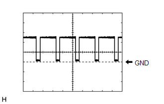
(c) Waveform 3:
|
Item | Content |
|---|---|
|
Terminal No. | K54-6 (BLW) - K54-4 (GND) |
|
Tool Setting | 2 V/DIV., 1 ms./DIV. |
|
Condition |
|
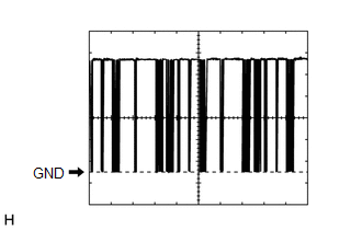
(d) Waveform 4:
|
Item | Content |
|---|---|
|
Terminal No. | K54-14 (LIN1) - K54-4 (GND) |
|
Tool Setting | 2 V/DIV., 20 ms./DIV. |
|
Condition | Ignition switch ON |
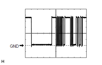
(e) Waveform 5:
|
Item | Content |
|---|---|
|
Terminal No. | z28-3 (BUS) - z28-2 (BUS G)*1 z29-3 (2A) - z29-2 (1A)*2 |
|
Tool Setting | 2 V/DIV., 2 ms./DIV. |
|
Condition | Ignition switch ON |
- *1: for Dual Type
- *2: for Single Type
CHECK AIR CONDITIONING CONTROL ASSEMBLY

HINT:
Check from the rear of the connector while it is connected to the air conditioning control assembly.
|
Terminal No. (Symbol) |
Wiring Color | Terminal Description |
Condition | Specified Condition |
|---|---|---|---|---|
|
K26-2 (IG+) - K26-6 (GND) |
GR - W-B | Power source (IG) |
Ignition switch off | Below 1 V |
|
Ignition switch ON | 11 to 14 V | |||
|
K26-6 (GND) - Body ground |
W-B - Body ground | Ground for air conditioning control assembly |
Always | Below 1 V |
|
K26-9 (LIN1) - Body ground |
LG - Body ground | LIN communication signal |
Ignition switch ON | Pulse generation (See waveform) |
|
K26-11 (ILL+) - Body ground |
W - Body ground |
Illumination signal | Light control switch in off position |
Below 1 V |
| Light control switch in tail or head position |
11 to 14 V | |||
|
K26-15 (ILL-) - Body ground |
B - Body ground | Illumination signal |
Always | Below 1 V |
(a) Waveform:
|
Item | Content |
|---|---|
|
Terminal No. | K26-9 (LIN1) - Body ground |
|
Tool Setting | 2 V/DIV., 20 ms./DIV. |
|
Condition | Ignition switch ON |
READ NEXT:
 Diagnosis System
DIAGNOSIS SYSTEM DESCRIPTION Air conditioning system data and Diagnostic Trouble Codes (DTCs) can be read through the Data Link Connector 3 (DLC3) of the vehicle. When the system seems to be malfuncti
Dtc Check / Clear
DTC CHECK / CLEAR DTC CHECK USING TECHSTREAM (a) Connect the Techstream to the DLC3.
(b) Turn the ignition switch to ON. (c) Turn the Techstream on.
(d) Enter the following menus: Body Electrical /
Data List / Active Test
DATA LIST / ACTIVE TEST DATA LIST NOTICE:
In the table below, the values listed under "Normal Condition" are reference values. Do not depend solely on these reference values when deciding whether a p
SEE MORE:
Removal
REMOVAL CAUTION / NOTICE / HINT
The necessary procedures (adjustment, calibration, initialization, or registration) that must be performed after parts are removed and installed, or replaced during front lower ball joint assembly removal/installation are shown below. Necessary Procedures After Part
Motor Control Relay Stuck ON (B2345)
DESCRIPTION This DTC will be stored if the operation of the sliding roof or roof sunshade is suspended and a pulse input of 10 Hz or more is detected when the motor relay is off. Sliding Roof
DTC No. Detection Item
DTC Detection Condition
Trouble Area
B2345 Motor Cont
